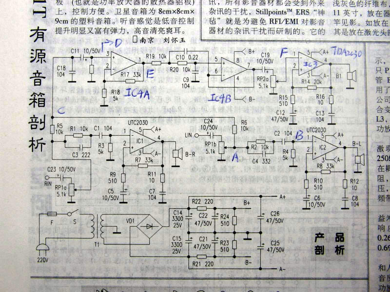
Working principle, as shown in the figure: mainly divided into three parts. These are the power supply circuit, the satellite box amplifier circuit, and the subwoofer circuit.
1. Power circuit (the bottom part of the drawing): 220V mains enters the transformer primary after the fuse (F) and switch S, and the secondary output of the transformer
Double 12V AC, double 12V is sent to the bridge rectifier circuit circuit composed of VD1, after the bridge rectifier and C14, C15 (3300UF / 25V) filtering, The output no-load voltage is about plus or minus 16V (root number 2 times 12V), that is, A + is plus 16V, and A- is minus 16V. Positive and negative 16V are three power amplifier chips TDA2030, UTC2030 provide power. After the buck of R21 and R22 is applied to the other channel, the positive and negative 12V output from B + and B- is the bass preamplifier and The low-pass filter IC4 provides the power supply voltage.
In this drawing, the preamplified power supply does not use the 78/7912 three-terminal voltage regulator circuit. Mill lovers can also consider when replacing two 3300UF capacitors. Add LM7812 / 7912 to provide a more stable working voltage for the front.
Second, the left and right channel amplifier circuit (satellite box power amplifier circuit), because the principle of the left and right channels is completely consistent. Here I will only use the left channel of the drawings as an example to make an introduction. As shown in the figure: RIN is the signal input terminal, enters the volume potentiometer through the coupling capacitor C23, (the volume potentiometer consists of three pins, and C23 is the input terminal, The output terminal is also called the sliding terminal, and the other pin is the ground terminal. After adjusting the volume, the signal enters the treble boosting circuit composed of R1 / C3. This circuit can boost a certain amount of High-frequency signals make the sound clearer. After that, the signal enters the left channel power amplifier through the coupling capacitor C1. The pin 1 of the model is UTC2030. After power amplification, the The fourth pin of 2030 is output to push the satellite box to sound. In the figure, R7 is the feedback resistor, and R7 / R9 is the magnification factor that determines the 2030 chip. Therefore, adjust the resistance of R7 , You can adjust the magnification. R11 / C7 is the speaker compensation network.
3. Subwoofer circuit. From the left and right channels through two 10K resistors R5 and R6 to the C11 coupling capacitor, the signal then enters IC4, pin 3 of model JRC4558, as shown in the figure IC4A is a subwoofer preamplifier. R201T sets this amplifier's magnification to about 6 times. (R17 / R18), after pre-amplification, to ensure sufficient The driving voltage is large enough to obtain a sufficiently large volume. Pin 1 of 4558 is the front output, and enters the low-pass filter composed of IC4B, C9, C10, and R20 after R19. The role of the low-pass filter is to cut off low-frequency signals below 200 Hz, and R20 and C10 determine the cutoff frequency. (The specific cut-off frequency setting of each manufacturer is slightly different). After IC4B output ---- C19, it is connected to the input terminal of the volume potentiometer. After adjusting the volume of the subwoofer, the output from the slide terminal of the potentiometer enters the subwoofer amplifier IC3 TDA2030A, the principle of this circuit is consistent with the satellite box amplifier. Pin 4 is the output terminal, which pushes the woofer to sound.
The above is the basic working principle of R201T. By the way, there is an error in the above figure: that is, the 1-pin input terminal of TDA2030A should be marked as "+" which is the non-inverting input terminal. Pins 1 and 2 on the drawing are reversed.
Note: Rambler R1900TII, 1800TII. Light cavalry V23SE, Hivi M200, M20W, M20L T120. The chip LM1875T used in its. TDA2030A consistent 2.1 Speaker repair method:
Master the basic principles of the circuit, and repairs will be more efficient. In fact, overhauling the audio system is like paying attention to "watching, smelling, asking, and cutting" like a doctor looking at a patient.
Things to do before overhauling: don't rush to start when the audio encounters a malfunction. First ask the user's use of the situation: Before and after the obstacle, the sound has What is abnormal, such as There is no "kaka" noise, whether there is any smell, or whether there is smoke from the sound, so that you can quickly understand the sound Ringing state. In case of failures such as silent sound or mono sound, do not rush to determine the failure of the sound itself; first, first eliminate the signal source and The problem with the connection line. For example, check if the computer is muted, is the system volume adjusted to the minimum position? ? ? ? Whether balance control In the middle? ? ? ? After confirming that there is no problem with the sound card or DVD / CD signal, you must also check the output audio cable. Will cause mono or noise. Also. Also check the connection clips of the satellite box for looseness. (Sometimes you can swap the two satellite boxes to confirm Dingwei The quality of the star box and the power amplifier circuit); make sure that the signal source and the connection cable are no problem, and only decide to disassemble your speaker for maintenance when the fault has not been eliminated.
The following uses R201T as an example to introduce several common troubleshooting methods for speakers:
1. There is no response when starting up, neither the satellite box nor the subwoofer sound. (At this time, there is no response when adjusting the two volume potentiometers). This failure can basically be regarded as a power failure. (Because the probability of three power amplifier chips being damaged at the same time is very low). If the insurance tube of the multimedia audio is installed outside. We can unscrew the safety cover and take out the safety tube, Observe: if Insurance has broken down, and do n’t rush to replace it with a new one. We can observe the situation of insurance damage: if the fuse is only broken in the middle or both ends, there is no obvious Burn marks trace. It can be estimated that the insurance was accidentally damaged. (Because of the high mains voltage, etc.) At this time, the replacement of the insurance tube with the same specification can generally be excluded. (If the insurance tube is installed To the main box , You need to remove the cover to remove the insurance).
If the wall of the fuse is burnt black, it is estimated that the transformer is burned (or short-circuited between turns). In addition, short-circuiting of components in the rectifier or filter circuit will also cause this phenomenon. At this moment We can observe the change Check whether there is any smell in the compressor, and see if there are any signs of burning. At the same time, you can use a multimeter to check whether the secondary output voltage. If the transformer output is normal, then check it, four rectifiers Whether there is a breakdown short circuit , Whether the capacitor is short-circuited, etc. Until the short-circuited component is detected.
2. Mono. For example, if the left channel is silent, we can remove the left channel satellite box and access the right channel satellite box. If the satellite box sounds at this time, the fault can be confirmed The reason is left The satellite box speaker is faulty or burned. If the right satellite box is connected, the fault remains, indicating that the speaker is good, but the left channel amplifier circuit is damaged. . (You can also put R201T behind Audio input cable Switch left and right channels to judge the working status of 2.1 speakers). So, how to repair the left channel power amplifier circuit? ? ? ? ? Let's look at the drawing, I marked A in the picture , B, C, D, E, several "Key points". IC2 is a left channel amplifier circuit, we can use a simple and effective "signal injection method" (also called signal interference method), specifically, it can be used for medical treatment Used metal tweezers or He used a small screwdriver, (hands touching the metal part), directly touching point B in the picture. That is, pin 1 of the power amplifier chip. At this time, the loudspeaker should have a large "click" interference sound. If not, Then basically The power amplifier chip has been OVER. We just use the same type of chip replacement. UTC2030 can be directly replaced with UTC2030, TDA2030, TDA2030A. At the same time, it should also be noted that the R10 and C6 of the inverting input terminal of the TDA2030A are disconnected or damaged, which may cause sound blocking or even silence. In addition, there is a circuit board copper at point A --- B Foil break will also cause the left channel to be silent. Check above The premise of the repair method is: the working voltage of IC2 is normal. (That is, pin 3 is negative 16V, and pin 5 is about 16V).
3. No sound from the subwoofer. We can directly use the R * 1 block of the multimeter to measure the woofer. The speaker should have a small "kaka" sound, otherwise the speaker will be damaged. Horn normal In case, we The signal injection method is still used. In order to quickly find the fault point, interference is generally done from the "back" to the "front". That is, do the signal injection to the post-amplifier of the power amplifier first, Inject the signal in the previous stage.
As shown in the figure: the interference signal is injected at point F, and the woofer should have a “popping soundâ€; otherwise, the TDA2030 power amplifier circuit must be repaired. If the popping sound is normal, but the subwoofer does not work, We can check The volume potentiometer of the bass can't solve the problem after eliminating the problem of the potentiometer, then check IC4. IC4 has two functions, one is pre-amplification, one This is low-pass filtering. If IC 4 The power supply is abnormal or damaged, which will cause the silent failure of the subwoofer. (Note, pin 8 of IC4 is positive 12V and pin 4 is negative 12V). Before conducting the above inspection, We need to visually observe whether the circuit board is broken and whether the components are obviously burned. This way you can avoid detours.
Continued, TDA2030A is a relatively easy to damage device, except for the signal injection method. We can also use the following methods to quickly judge the quality of 2030-we first detect the chip Whether the power supply is normal, that is, 5 feet are positive 16V, and 3 feet are negative 16V. In the absence of signal input, the other three pins should be zero voltage. If the 4th pin is measured (Amplifier output) There is DC voltage output, (even reaching about 16V), make sure the chip is damaged. One point to pay special attention to: TDA2030A (LM1875) The pin 3 of the LED is connected to the heat dissipation contact surface. If there is no insulating sheet between the heat dissipation surface and the heat dissipation plate, keep in mind that the heat dissipation plate should not touch the ground wire or the power line Otherwise, the chip may be damaged.
4. When adjusting the potentiometer, the speaker has the noise of Kaka. This fault can be cleaned with WD-40. Reference: http: //? U = bbs & id = 20040216225824sb If the wear is severe, replace it with a potentiometer of the same specification.
5. There is "howling" sound or loud noise in the speaker. When a rectifier diode of the rectifier circuit breaks down or the filter capacitor fails. It may cause this malfunction. How to judge whether the filter capacitor is invalid? ? ? ? We can detect A +, A- voltage. The normal voltage should be around 15V. When it is detected that a certain group of voltage is only about 10V, It is estimated that the corresponding filter capacitor has failed. For example, if A + only has 10V, then C14 has failed and lost its filtering effect. Replace it with a capacitor of the same specification.
Sixth, the subwoofer has a loud "Weng Weng" sound when it is not playing music. Even if the input signal cable is unplugged, Weng Weng is still very large and cannot be eliminated. This phenomenon is generally The most likely cause of the faulty circuit of the bass channel is the damage of the TDA2030A chip. Causes the TDA2030 pin 4 to output a DC voltage, causing the speaker to emit a dull "Weng" sound, Just replace the power amplifier chip to solve the problem.
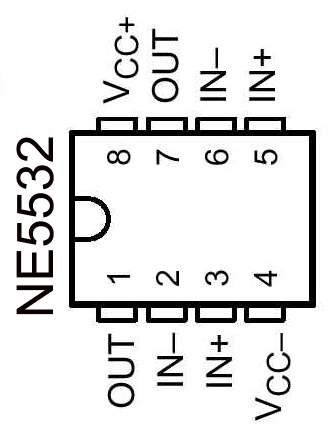
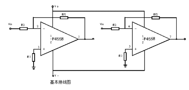
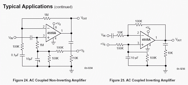
 See the three pictures in reply 5, we can quickly identify the pin sequence of NE5532 and TDA2030A. Color picture one: the pin in the middle is NE5532 (JRC4558) pin 1. The bottom figure is the identification of each pin of the dual op amp. At a glance.
NE5532 (JRC4558) pins: 1 is the output of the op amp, 2 is the inverting input, and pin 3 is the input. Pin 5 is the non-inverting input of the other op amp, pin 6 is the inverting input, pin 7 is the output. Pin 4 is the negative voltage , 8-pin positive voltage.
The actual picture in the middle is 2.1. The TDA2030A power amplifier chip commonly used in speakers. This chip is a dual in-line package. Count from left to right: feet 2 and 4 are close to the heat sink. The front row is followed by feet 1, 3, and 5. (LM1875 pins are exactly the same).
| 


