In recent years, the field of digital voice processing technology has gradually developed into two camps - traditional digital voice technology and new analog voice technology. The former is to convert the voice signal into a digital code by analog-to-digital conversion (A/D), and store it in various digital memories (ROM, SROM, EEPROM, etc.), and then perform digital-to-analog conversion (D/A) synthesis. The analog voice has relatively poor sound quality and complicated structure. The new analog voice processing technology directly accesses the voice analog quantity into a special non-volatile analog memory, which has good sound quality and simple structure. The voice recording and playback chip APR9600 takes advantage of the latter technology, the new analog voice processing technology.
During recording, the external audio signal is amplified by the microphone amplifier with automatic gain adjustment inside the chip APR9600. It is processed by the internal filter and sampling circuit and stored in the dedicated flash memory FLASHRAM in analog mode. Since the FLASHRAM is a non-volatile device, it is broken for a long time. Electronic voice will not be lost. During playback, the on-chip read logic takes the signal from the FLASHRAM, sends it through a low-pass filter to the power amplifier, and then directly pushes the external speaker to play.
1 pin function
The APR9600 is a 28-pin dual in-line standard package DIP chip. The function description of each pin is shown in Table 1. 
APR9600 working voltage 4.S~6.SV, quiescent current 1uA, working current 2SmA, driving power 12mW (external speaker 16Q).
2 control mode and typical application circuit
The typical application circuit of APR9600 is shown in Figure 1. The APR9600 has a variety of modes for recording and playback control, which provides great convenience for ordinary users. In general, it is divided into serial control and parallel control modes, which are implemented by the settings of chips MSEL1, MSEL2 and /M8. The typical application circuit of APR9600 is shown in Table 2. 

In the parallel control mode, each segment has a corresponding key control. The recording and playback of any segment does not affect other segments. The control is simple and can be divided into up to eight segments. It is applicable to several segments of speech that are irrelevant, and there is no order at all. Place; in the serial control mode, the language is recorded and played in a certain order, the control keys are few, and the segmentation control is inconvenient. It is suitable for the case where several segments of speech are related to each other and have a certain order.
3 Application in telephone remote control system
The author designed and produced a multi-channel telephone remote control, through which people can use the telephone to switch control and timing functions of various household appliances anytime and anywhere. Because of the remote control distance of telephone lines across provinces and cities. The system adopts single-chip control to realize duplex communication by using voice chip, and achieves prompts for different operations and information feedback on the state of the controlled party, so that the operator can timely understand the controlled party information, and make the product interactive and intelligent.
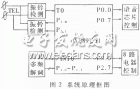
The overall circuit block diagram is shown in Figure 2. In addition to the AT89CS1 as the main control CPU unit, the whole circuit also has ringing detection, analog off-hook, dual-tone multi-frequency demodulation, voice chip control, and electric drive unit. 
The system APR9600 is pre-set to the eight-stage parallel control mode. The "MSEL1", "MSEL2", and "/M8" terminals of the APR9600 are set to 1 (connected to the positive power supply). Set the RE terminal to the recording state, press and hold /M1 to start recording the first segment, and the loose button will stop. Press /M2 again to record the second paragraph, so press and hold /M8 to record the eighth paragraph. The eight-segment voice recorded by this system is shown in Table 3. 
The playback of the corresponding voice segment is triggered by the software. The voice chip SP+, SP-end, is connected to the telephone line, and is fed back into the telephone handset. The user can hear the prompt from the telephone control system voice chip to perform corresponding operations.
The overall structure of the software is divided into five parts: (1) system initialization; (2) ring flow detection; (3) password comparison; (4) channel on/off; (5) change password. The process is shown in Figure 3. 
The following describes the distribution skills of limited speech resources in this system, mainly introduces how to use two voices. 
The voice feedback of the state of the 8-channel controlled device. According to the normal idea, each device should have two voice prompts before the operation and after the operation. The 8-channel device needs 16 segments of voice. In the actual programming, the state of the eight-way controlled device is registered with a one-byte RAM unit, as shown in Table 4.
The 8 bits of the RAM unit respectively represent the state of the 8-way electrical device (1 means open, 0 means off). The binary bit corresponding to the RAM unit is modified by software query, and when it is 1, the feedback voice “the circuit appliance has been turned onâ€, when it is 0, the feedback voice “the circuit appliance has been turned offâ€. Due to space limitations, the specific procedures are omitted. This design method is also applicable to other types of voice chips.
This article refers to the address: http://
Vape Pen,OEM/ODM Vape Pen,Filling Portable Disposable Vape Stick,Pen Style Vape Pen
TSVAPE Wholesale/OEM/ODM , https://www.tsvaping.com