High-performance op amps and dedicated software on the PC facilitate the design of broadband active filters, but this does not solve any specific application problems. For video filters, specific applications and signal formats bring subtle differences to each circuit design. The following are two main types of video applications.
Anti-aliasing filter: This type of device is placed before the analog-to-digital converter (ADC) to attenuate components above the Nyquist frequency in the signal, that is, signal components that are more than half the ADC sampling rate. The response of these filters is usually designed to be as steep as possible in order to filter out signals above the cut-off frequency¹ as much as possible. For ITU-601 and other applications, such performance is achieved by combining analog filters, digital filters, and oversampling ADCs. For applications such as PC images, a small amount of filtering is sufficient.
Reconstruction filter: also known as (sinx) / x or zero-order hold corrector, this type of device is placed after a digital-to-analog converter (DAC) to eliminate multiple images brought by sampling, not to eliminate DAC clock crosstalk. Reconstruction filters rarely have the same selectivity as anti-aliasing filters, because the hold function of the DAC also has a filtering effect-this effect reduces the requirement for selectivity, but brings a loss to the response. Existing video signal standards include RGB, component video, composite video and RGB PC images.
All applications and standards hope that the video filter can achieve "phase linearity", which is required by the group delay (delay at different frequencies) characteristics. The required phase linearity depends on the specific application and video format. For example, anti-aliasing filters and component formats are more stringent than reconstruction applications and composite video. The requirements for various applications and standards are specified by NTSC, PAL / DVB, ITU, SMPTE and VESA.
This article will compare different filters to determine the best design for a given application or format. The ratios of GBW and cutoff frequency of Rauch and Sallen-Key filters are compared, and pre-distortion and parametric sensitivity techniques are used in the design to obtain high accuracy. The filters examined include: ITU-601 anti-aliasing filter 20MHz anti-aliasing and reconstruction filter HDTV reconstruction filter filter and its characteristics Whether it is used for anti-aliasing or reconstruction, the filter must have low-pass characteristics To enable the frame rate of the video to pass. Therefore, designers need to carefully consider AC coupling. Low-pass filters can be classified according to their amplitude characteristics or polynomials used to describe it (Bessel, Butterworth, Chebyshev, or Cauer). Figure 1 shows the characteristics of these filters after normalization to a 1-rad bandwidth. Usually the filter with the best selectivity and the smallest number of poles (reducing cost) should be selected, but the additional requirements for phase linearity limit the range of options.
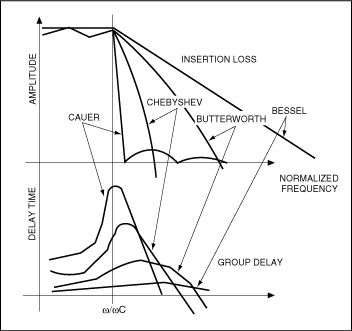
Figure 1. Normalized to 1-rad bandwidth, the relationship between the amplitude of various filters and the group delay and frequency. The phase linearity and the phase linearity of the group delay filter determine the envelope delay or The relationship between group delay (GD) and frequency. The flat group delay indicates that all frequencies are delayed by the same time, which is beneficial to the maintenance of the signal waveform in the time domain. Therefore, the group delay difference is more important than the absolute group delay. There is another independent parameter called channel difference, which is used to measure the "time compliance" between channels, and it should not be confused with group delay.
For video, to what extent is the group delay difference acceptable? Why? The answer depends on the specific application and video format. For example, ITU-470 has very loose regulations on group delay of composite video signals. However, ITU-601 is much stricter in order to ensure the stability of video playback, not only for MPEG-2 compression, but also for controlling the phase jitter before serialization. So, what filter characteristics should be considered to ensure phase linearity?
The group delay curve in Figure 1 shows a peak at the cutoff frequency (ω / ωc = 1). This is caused by the steep phase change near the cutoff frequency. In order to have a general concept, take a 3-pole, 6MHz Butterworth filter as an example, the group delay difference is about 20ns to 25ns within its bandwidth. Increasing the number of poles or the selectivity of the filter will increase this difference. Other more special filters used to reduce group delay differences include Bessel, phase approximation, Thompson-Butterworth, and LeGendre. Nevertheless, the most commonly used filters in video are Butterworth filters. Group delay of component video All video formats and applications are sensitive to group delay differences. Sensitivity depends on the number of signals and their bandwidth. The composite NTSC / PAL system has only one signal, and the group delay is specified in ITU-470. This requirement is easily met. Both RGB and component video contain multiple signals. Each channel of the RGB signal has the same bandwidth and the component video is different, so for RGB, group delay matching is easier and component video is more difficult.
Because the bandwidth of the Pb and Pr signals is only half of the luminance (Y) signal, their group delay is twice that of the Y signal³. One solution is to add a delay stage to slow down the Y signal. Another solution is to double the sampling rate of the Pb and Pr signals to make the signal bandwidth equal, that is, increase the sampling rate of 4: 2: 2 to 4: 4: 44, so that the signal can be treated as RGB. The extra Pb and Pr samples are discarded during anti-aliasing or averaged in reconstruction applications.
Another component video format, S-VHS, is confusing. The Y channel is the same as YPbPr, but the chrominance signal (C) looks more like band-pass filtering rather than low-pass filtering. For YPbPr signals, band-pass filtering can cause group delay and synchronization problems, so it cannot be used. Unless analog coding is performed, the Y and C signals can be low-pass filtered using the same filter. The benefits of S-VHS in terms of bandwidth make it understandable in terms of delay equalization. S-VHS is commonly used in video reconstruction applications. The main concern of such applications is the correct synchronization between Y and C. After selecting the filter characteristics of the op amp, the next step is to implement it with an actual circuit. The most commonly used single op amp circuits are the Sallen-Key filter in the same phase configuration and the Rauch filter in the reverse phase configuration. For operational amplifiers operating in broadband video applications, an important consideration is the minimum gain-bandwidth (GBW). The video signal is a large-scale signal, typically 2VP-P, so the large signal GBW should be considered. Do not confuse this parameter with 2VP-P 0.1dB GBW, which is much smaller.
For the filter circuit, how much should the GBW of the op amp be higher than the cut-off frequency of the filter? For Rauch (inverted) filters, the phase angle parameters are:
Arg [K (jω)] inv =-(ωc / GBWrad) (1 + Rf / Ri)
For Sallen-Key (in-phase) filter:
Arg [K (jω)] noninv = π- (ωc / GBWrad) (1 + Rf / Ri)
Among them, Rf and Ri are the resistance that set the gain, the unit is Ω, GBWrad is the gain bandwidth product of the operational amplifier, ωc is the cut-off frequency of the filter, the unit is radian / second. Set appropriate gains for given Rf and Ri5, and solve (ωc / GBWrad). Rf / Ri = 1 in unity-gain Rauch circuit, and Rf / Ri = 0 in Sallen-Key circuit. Therefore, for the same phase error, the GBW required by the Sallen-Key circuit is half that of the Rauch circuit. As the required gain increases, their gap in GBW narrows, and the advantages of Sallen-Key filters become smaller, but there are other issues to consider. Any limited GBWrad / ωc ratio of predistortion, bandwidth, Q, and parametric sensitivity will shift the closed-loop pole of the filter. This is why the bandwidth ωc of the actual filter is always smaller than the design expectation6. Increasing the design bandwidth can compensate for this problem, which is the so-called pre-distortion technology. Using the calculation formulas of Sallen-Key and Rauch circuits (listed in Table 1 and Table 2 respectively), we can calculate the design bandwidth that meets the actual bandwidth requirements. Component tolerances must also be taken into account.
In order to determine the component tolerance, a sensitivity factor of 7: SXY is introduced, which is the ratio of the parameter change amount of the component X to the parameter Y change amount it causes. For example, Table 1 shows that Q in the Sallen-Key circuit has a relatively large sensitivity to changes in C1 and C2 (compare Rauch circuit). This means that Sallen-Key circuit has lower tolerance to parasitic parameters than Rauch circuit. The key is that SXY allows us to predict this effect and take corresponding countermeasures in the design. Then you can consider some typical designs.
Table 1. Component sensitivity and BW and Q predistortion formula (Sallen-Key type, ωO = 1rad / s)
| SensiTIvity FuncTIon SXY | Gain K = 3-1 / Q (R1 = R2 = C1 = C2 = 1) | Gain K = 1 (R1 = R2 = 1) | Gain K = 2 (R1 = C1 = 1) |
| SXω (x = R1, R2, C1, C2) | -1/2 | -1/2 | -1/2 |
| SKQ | 14 | 50 | 10 |
| SR1Q | 4.5 | 0 | 4.5 |
| SR2Q | -4.5 | 0 | -4.5 |
| SC1Q | 9.5 | 1/2 | 5.5 |
| SC2Q | -9.5 | -1/2 | -5.5 |
| SRaK | -9/14 | N / A | -1/2 |
| SRbK | 9/14 | N / A | 1/2 |
| ωc (actual) | ωc (design) [1-1/2 (3-1 / Q) 2ωc / GBW] | ωc (design) [1-ωcQ / GBW] | — |
| Q (actual) | Q (design) [1 + 1/2 (3-1 / Q) 2ωc / GBW] | Q (design) [1 + ωcQ / GBW] | — |
Table 2. Element sensitivity and BW and Q predistortion formula (Rauch type, ωO = 1rad / s)
| SensiTIvity FuncTIon SXY | Gain K = 1 (R1 = R2 = R3 = 1) | Gain K = 2 (R1 = 1, R3 = Ho, R2 = (Ho / 1 + Ho)) | Gain K = 2 (C1 = 1, C2 = C1 / 100) |
| SXω (x = R1, R2, C1, C2, SR1ω = 0) | -1/2 | -1/2 | -1/2 |
| SR1Q | 1/3 | 1/3 | 1/3 |
| SR2Q | -1/6 | 0 | 0 |
| SC1Q | 1/2 | 1/2 | 1/2 |
| SC2Q | -1/2 | -1/2 | -1/2 |
| SR3K | 1 | 1 | 1 |
| SR1K | -1 | -1 | -1 |
| SR3Q | 1/6 | 0 | 0 |
| ωc (actual) | ωc (design) [1-3ωcQ / 2GBW] | — | — |
| Q (actual) | Q (design) [1 + 3ωcQ / 2GBW] | — | — |
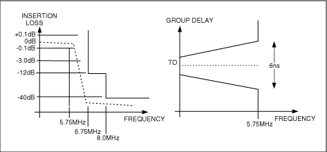
Figure 2. This filter template represents the anti-aliasing filtering required by the ITU-R BT.601-5 standard
Using software or normalized curve 8, we will find that a 5-pole Butterworth filter with a -3dB bandwidth of 8.45MHz can meet the selectivity requirements, but does not consider the group delay. For the latter, a delay stage is required, and for this circuit, the operational amplifier parameters that need to be focused on are 0.1dB and the 2VP-P bandwidth is 9. Apply this value to equations 1 and 2 to obtain an accurate design. Figures 3a and 3b give a schematic diagram suitable for this type of application, and show its gain and group delay characteristics with a curve. This design is based on a four-fold oversampling system.
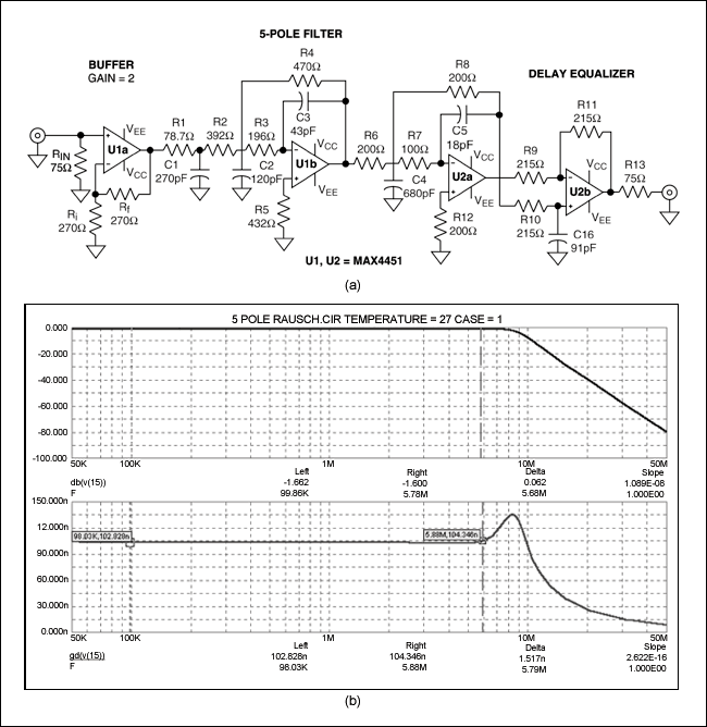
Figure 3. This schematic (a) and output response (b) show the 5-pole 5.75MHz Butterworth filter for ITU-601 anti-aliasing, which uses a Rauch circuit and a delay equalizer.
The next thing to consider is PC video. VESA does not specify a template for anti-aliasing or reconstruction filters. The XGA resolution (1024 x 768, 85 Hz) has a sampling rate of 94.5 MHz, and the Nyquist frequency is 47.25 MHz. To obtain> 35dB of attenuation at the Nyquist frequency, a 20MHz, 4-pole Butterworth filter of the Rauch type is used (Figures 4a and 4b). The MAX4450 / MAX4451 are still selected because of their excellent transient response and large signal bandwidth (175MHz at 2VP-P).
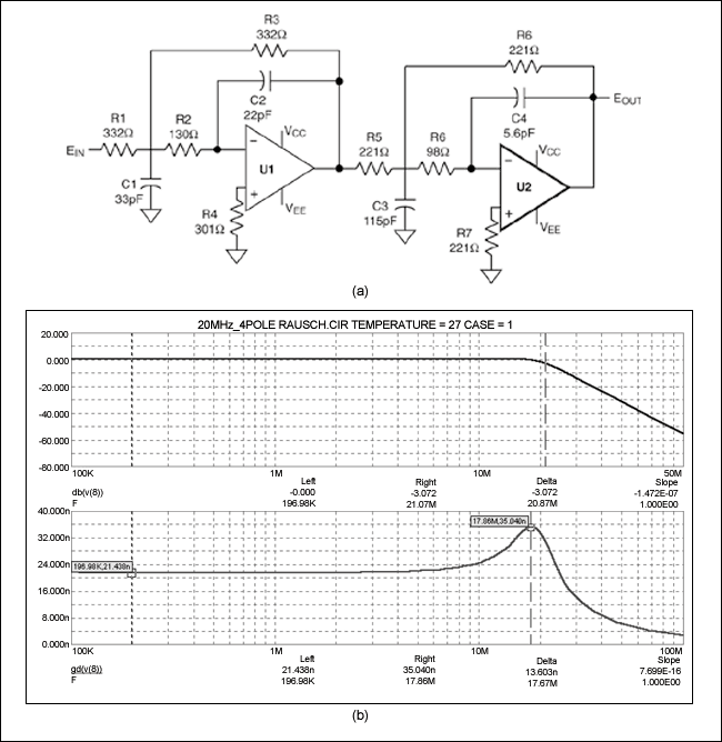
Figure 4. The schematic (a) and output response curve (b) describe a 4-pole 20MHz Butterworth filter for XGA image anti-aliasing, using a Rauch circuit. The reconstruction filter after the reconstruction filter DAC is one of the applications that is not well understood. Many designers believe that the reconstruction filter is introduced to filter out the sampling clock, but this is far from the truth. When the signal is sampled, the sample contains multiple repetitive signal images, respectively aligned to the harmonics of the sampling clock. The reconstruction filter will filter out all other signals except the baseband samples. If the anti-aliasing filter achieves its purpose, then the DAC output looks like the image A in Figure 5. Next, all samples to the right of it should be filtered out. Therefore, the requirements for reconstruction are similar to anti-aliasing. However, because each sample stays only for an instant, the DAC will hold each sample for one clock cycle. In this way, we are familiar with the approximation of a diagonal line. Stepped waveform.
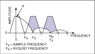
Figure 5. Typical DAC output spectrum versus sampling frequency (FS) and Nyquist frequency (FN)
The hold function is equivalent to a digital filter, and its characteristic 10 is similar to a Butterworth or Bessel filter (Figure 6). Note that the response is reduced by 4dB at half the sampling frequency. The second purpose of the reconstruction filter is to compensate for this loss, which requires an amplitude equalizer like the circuit in Figure 7a. The equalizer is constructed on the basis of a delay circuit and has a response similar to a Bessel filter. It can be designed according to the DAC sampling rate (FS). Figure 7b shows the DAC frequency response with and without the amplitude equalizer. Similar to the delay stage, it can be included in any reconstruction filter.
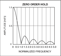
Figure 6. The "hold" function of the DAC produces a (sinx) / x response with the zero point at an integer multiple of the sampling frequency.
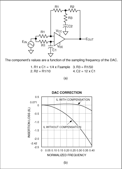
Figure 7. This figure shows the DAC output (b) with or without (sinx) / x correction (provided by the amplitude equalizer circuit (a))
Keeping the response also has a pole aligned with the sampling clock, which can completely eliminate the clock. However, most reconstruction applications still use clock attenuation as their quality factor. Now that we understand the function of the reconstruction filter, we can proceed to design.
The most common requirements for NTSC / PAL video reconstruction are attenuation> 20dB at 13.5MHz and> 40dB at 27MHz. Ωc depends on the adopted video standard. For two reasons, we chose the 3-pole Butterworth filter of Sallen-Key structure. First, its gain (+2) is suitable for driving reverse-terminated cables. Secondly, its group delay difference can be adjusted, so that without delay equalizer we can achieve the best performance by adjusting the group delay (Figures 8a to 8d show the NTSC and PAL designs, as well as their gain and group Delay characteristics). These applications usually include digital amplitude correction for the DAC, which can easily be added if necessary.
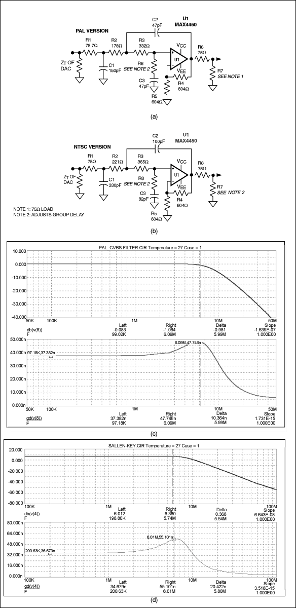
Figure 8. For the reconstruction filter with group delay adjustment, the amplitude and group delay response curves of the PAL version (a) are shown in (c), and the amplitude and group delay response curves of the NTSC version (b) are shown in (d).
A circuit for XGA is also shown. It is a 20MHz, 3-pole Butterworth filter using Sallen-Key structure. In order to achieve amplitude correction, it also includes the circuit in Figure 8 (Figures 9a and 9b). Complementing the anti-aliasing filter of Figure 4, the filter has a gain of +2 and is used to drive a 75Ω coaxial cable terminated in reverse.
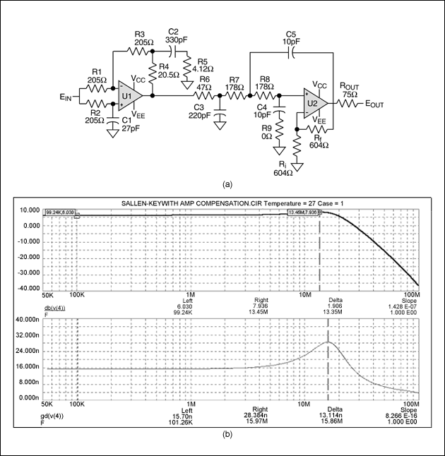
Figure 9. A 3-pole 20MHz Butterworth filter with (sinx) / x compensation for XGA reconstruction (a). The output response curve is shown in (b).
The last application is a reconstruction filter for HDTV. According to the template specified by SMPTE 274 and 296M, its center frequency ωc = 0.4 x FS = 29.7MHz. Amplitude correction for DAC is usually already included, but group delay compensation must be added. The result is a 30MHz, 5-pole Sallen-Key filter (Figure 10) with an attenuation of> 40dB at 74.25MHz. It also includes a group delay stage with a gain of +2 to drive a 75Ω coaxial cable terminated in reverse.
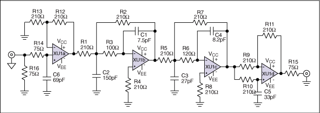
Figure 10. 5-pole 30MHz reconstruction filter for HDTV, including DAC amplitude correction. Whether the actual problem in active video filter design is manual design, software-aided design, or a filter obtained by combining these two methods, the actual response curve may not fully meet expectations. One reason is that there is a discrepancy between the calculated response and the actual response obtained using standard component values.
Selecting a standard (5%) value capacitor and deriving the resistance value can minimize the error. The reason is very realistic-you can buy capacitors with 1% or 2% tolerance, but the accuracy of the capacitance is only 5%, and for resistors, resistors with 1% tolerance and 1% accuracy are easily available. The components selected in this way can provide the best consistency and the most accurate amplitude response.
After the filter is constructed, instability and oscillation may occur. If this happens, short the input to ground to see if it continues to oscillate. If the oscillation stops, it means that the impedance is too high, and reducing the design impedance can eliminate the oscillation. But if it continues to oscillate, please note whether the oscillation frequency is close to or below the cut-off frequency of the filter. If so, the oscillation may be caused by components or parasitic parameters. If the oscillation frequency is higher than the cutoff frequency, it may be caused by the op amp or circuit board layout.
A good layout is like a work of art, but it is based on some simple principles. It is important to provide a clean supply voltage and a solid ground, which means filtering with low ESR capacitors, sometimes a regulator. The loop connected by the bypass capacitor must be as small as possible, otherwise the parasitic inductance will resonate with the capacitor. A good ground plane is critical to a good analog design, but as the bandwidth increases, it may introduce parasitic capacitance and make the filter unbalanced. To avoid this problem, remove the affected component and the ground plane under the trace.
References At the cut-off frequency, the filter response drops by -3dB. Taylor and Williams, Electronic Filter Design Handbook, McGraw Hill, ISBN 0-07-070441-4. Cit. 4: 2: 2 sampling initially represents the oversampling multiple of the color subcarrier. ITU-601 changed the subcarrier frequency to 3.375MHz. 4: 2: 2 means sampling at 13.5MHz and 6.75MHz respectively. In the case of the same phase, Rf / Ri = 0; in the case of the reverse phase, Rf / Ri = 1. EJ Kennedy, Operational Amplifier Circuits: Theory and Applications. Defined by HW Bode in Network Analysis and Feedback Amplifier Design (D. Van Nostrand, Princeton NJ, 1945). Taylor and Williams, op. Cit. MAX4450 / MAX4451 data sheet. The Sinc function in mathematics is (sinx) / x.
What features you consider more when you choose an university laptop for project? Performance, portability, screen quality, rich slots with rj45, large battery, or others? There are many options on laptop for university students according application scenarios. If prefer 14inch 11th with rj45, you can take this recommended laptop for university. If like bigger screen, can take 15.6 inch 10th or 11th laptop for uni; if performance focused, jus choose 16.1 inch gtx 1650 4gb graphic laptop,etc. Of course, 15.6 inch good laptops for university students with 4th or 6th is also wonderful choice if only need for course works or entertainments.
There are many options if you do university laptop deals, just share parameters levels and price levels prefer, then will send matched details with price for you.
Other Education Laptop also available, from elementary 14 inch or 10.1 inch celeron laptop to 4gb gtx graphic laptop. You can just call us and share basic configuration interest, then right details provided immediately.
University Laptop,Laptop For University Students,University Laptop Deals,Recommended Laptop For University,Laptop For Uni
Henan Shuyi Electronics Co., Ltd. , https://www.shuyipcs.com