GPS intelligent terminal is an important part of the intelligent transportation system (ITS system), which integrates satellite positioning technology (GPS), geographic information system (GIS) and wireless communication technology. At present, the satellite positioning terminal is usually composed of 8-bit/16-bit single-chip microcomputer, GSM/GPRS communication module, GPS module, LCD liquid crystal display, etc., and adopts a split structure in which the liquid crystal part and the main control chipset are separated in two shells. Here is an introduction and design of an embedded intelligent terminal based on ARM920 processor and embedded Linux operating system, which combines GPS technology with CDMA network. The terminal has the ability to link the GPS terminal’s dynamic position, time, status and other information to the control center in real time through the CDMA wireless network, display it on an electronic map with geographic information processing and query functions, and check the terminal’s accurate position, speed, Basic information such as movement direction and terminal status are monitored and inquired; alarms (including active alarms and automatic alarms); display scheduling information; external device data collection, local temperature collection, and remote monitoring functions.
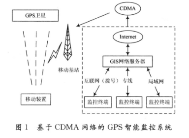
1 Overall design of GPS intelligent monitoring systemThe communication method between the GPS intelligent terminal and the monitoring center is an important factor affecting the function of the entire ITS system. In order to solve the problem of insufficient data transmission in the current terminal using GSM and GPRS networks, the design adopts CDMA 1X network, its theoretical transmission rate can reach 300 Kb/s, the data transmission rate is high, it is always online, and the entire Internet can be accessed based on the IP protocol; It is charged according to traffic and the price is reasonable; it has good scalability and covers most indoor areas and sea areas within 120 km from the coastline. There are basically no blind spots. The communication speed is much higher than the GPRS network, which is more suitable for large data volume and real-time transmission monitoring, and it is easy to smoothly transition to the 3G mobile communication system. The GPS intelligent monitoring system is composed of GPS intelligent terminals, CDMA network, Internet network, and monitoring center, as shown in Figure 1.
2.1 Platform introduction
The mobile terminal designed with ARM processor and embedded technology, compared with the terminal with 8-bit/16-bit single-chip microcomputer as the central processing unit, both the function and the man-machine interface have been significantly improved. It is microprocessor technology Important development. Here chooses AT91RM9200 processor of Atmel Company as the main controller. The core belongs to the ARM chip specially used for industrial control, has a wide operating temperature and other good industrial parameters, and integrates a wealth of system application peripherals and standard interfaces; it can reach a processing speed of 200 MIPS at a main frequency of 180 MHz ; External bus interface EBI. ; Two USB 2.0 host ports and one USB 2. O device port; a 10/100 Mb/s Ethernet communication interface; 4 synchronous/asynchronous serial ports; multiple serial data paths; support I2C, I2S, etc. Its abundant external equipment and data transmission characteristics are the main reasons for choosing it as the main controller.
2.2 Hardware design
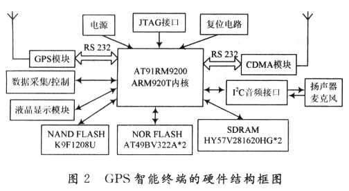
The hardware system constitution of GPS intelligent terminal is shown as in Fig. 2.
2. 2. 1 ARM main control module
The serial ports UART2 and UART3 of AT91RM9200 communicate with the CDMA module and the GPS module respectively. In the actual communication, both connections are added with a conversion circuit from LVTTL level to RS 232 level. AT91RM9200 receives the position information sent by the GPS module from the serial port 3, parses the useful data and encapsulates it, and then delivers it to the CDMA module through the serial port 2 in the specified format, and then connects to the Internet through the CDMA network and finally sends it to the ITS monitoring center; receives and analyzes the ITS The short message command sent by the control center is used for uploading and positioning according to the command; the operating status of the system and the information sent by the ITS control center are displayed on the LCD screen.
2.2.2 CDMA communication module
The CDMA module is the communication basis of the entire system. The CDMA communication module FD810 from Fidelix is ​​used in the design. The Qualcomm MSM6025 chip embedded in the module supports CDMA20001x wireless data transmission in addition to basic calls and SMS messages. High-speed uplink and downlink rate and large buffer, the data transmission rate is as high as 153.6 Kb/s, and the built-in TCP/IP protocol stack can be remotely controlled through AT commands. DTGS-800 and AT91RM9200 realize data sending and receiving and AT command operation through serial port UART2.
2.2.3 GPS module
The GPS receiver module uses iTrax100 from Finland Fastrax. The module supports the data format of NMEA0183 and Sony ASCâ…¡ protocol. The GPS module sends data to AT91RM9200 in a fixed frame format through the serial port 3. The GPS module needs to be equipped with a dedicated GPS antenna to receive GPS satellite signals. Generally, in relatively open areas, it is necessary to receive more than 3 GPS satellite signals for accurate positioning.
2.2.4 Memory system
The memory system adopts 4 MB NOR FLASH, 64 MB NAND FLASH and 32 MB SDRAM. NOR FLASH exchanges data with the CPU through a 16-bit data bus to store Uboot, Linux kernel, and file system; NAND FLASH stores application programs as the system's data storage, such as loading electronic charts. In order to give full play to the data processing capability of the 32-bit ARM processor, two 16-bit HY57V281620HGs are selected in parallel to construct a 32-bit SDRAM to exchange data with ARM. SDRAM is mainly used as the program's running space, data and stack area in the system.
First, program Uboot, Linux kernel, and file system to NOR FLASH through the JTAG port, and program the application program to NAND FLASH. When the system starts, the CPU first reads the startup code from the reset address 0x0, and configures the NORFLASH memory containing the boot program Uboot to: Bank0, that is, the NCS0 pin of AT91RM9200 is connected to the CE terminal of the NOR FLASH chip AT49BV322AD, so The embedded Linux operating system can be started from NOR FLASH.
3 Software design of GPS intelligent terminalEmbedded Linux systems only need three basic elements: boot program, Linux microkernel, and initialization process. Transplanting embedded Linux means that the real-time kernel can run on other processors (CPU) or microcontrollers (MCU). Porting embedded Linux to the AT91RM9200 platform generally requires 4 steps: downloading the source code and establishing a cross-compilation environment, configuring and compiling the kernel, making a file system, downloading and debugging the kernel.
3.1 Application programming
Application programs include Uboot startup code, serial device driver, CDMA network data transmission program, GPS serial communication program, etc.
(1) Reset the system after power-on;
(2) Uboot initializes CPU, SDRMA, allocates address space, etc.;
(3) Uboot decompresses the compressed file of the Linux kernel into SDRAM, and Uboot transfers the control right to Linux.
The Linux kernel has two working modes: running directly on FLASH memory and loading into memory. The FLASH memory operation mode adopted here is relatively complicated, but the operation speed is faster;
(4) Start to execute the code in SDRMA, initialize the Linux kernel, complete the allocation of stack and interrupt, etc.;
(5) Load the serial port driver module to complete the initialization of the serial port;
(6) Run the CDMA network data transmission program and connect to the Internet through the CDMA network;
(7) Run the GPS serial communication program and send GPS data to AT91RM9200 through the serial port.
So far, a complete embedded monitoring system from GPS data collection to data transmission has been established.
3.2 Wireless access network procedures
After the terminal is connected to the Internet from the CDMA network, data transmission is carried out through the Internet. After the system is powered on and loaded into Linux, first initialize the CDMA module, set the port setting and baud rate setting (115 200 b/s); then enter the dial waiting state. Since the terminal is functionally mapped as a wireless modem, a PPP dial-up connection is required to log in to the network, the access number is #777, and the user name and password are both CARD. After starting the program, confirm whether the dialing is successful. If the dialing is successful, call the GPS serial communication program and network data transmission program; at the end of using the Internet, close the wireless connection.
3.3 CDMA network data transmission program
Under the Linux operating system, the monitoring terminal is connected to the Internet through the CDMA network, and the data is uploaded to the monitoring center. Socket Socket is a common API for network programming of many operating systems, and is a programming interface between the network application layer and the transport layer. The socket provides a large number of system calls and corresponding data structures for accessing the lower communication protocol. The network communication process of the process on Linux is the process of using the socket to transmit data. , Socket communication introduced in the article adopts connection-oriented TCP protocol.
The TCP application process of the client and server is shown in Figure 3. The client part first creates a local socket by Socket() and assigns a value to the server-side socket address structure; uses the Connect() function to make the local socket send a connection request to the server-side socket, and establish a TCP connection through a 3-way handshake; if If the connection is established successfully, use the Send() and Recv() functions to communicate with the server; when the communication is over, close the socket with Close().
The server part creates a socket by Socket() and assigns a value to the socket address structure; binds the socket with the Bind() function and listens for requests on the socket with the Listen() function; when the Accept() function accepts the request, it generates A new socket and description word, and connect with the client; using the Fork () function to derive a new child process to communicate with the client, the main process continues to process other requests.
3.4 GPS serial communication program
The GPS serial communication program analyzes the collected GPS data and vehicle status data; analyzes data such as time, longitude, latitude, speed and overspeed alarm, and transmits it to the AT91RM9200 through the serial port 3 in a fixed format. The working flow of GPS module is shown as in Fig. 4.
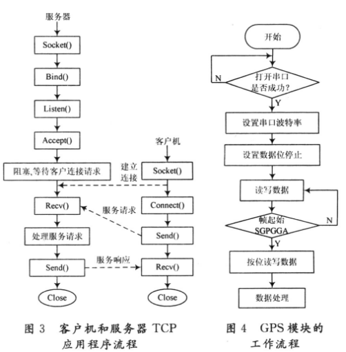
GPS received data adopts NMEA0183 format, serial communication parameters are 8 data bits, no parity check; 1 stop bit, no data flow control. The baud rate is set to 115 200 b/s. Determine whether the start of the frame is $G-PGGA, if so, read the GPS data bit by bit,
Under Linux, all hardware devices are regarded as ordinary files, and operations such as opening, closing, reading and writing devices can be completed through the same standard system calls as ordinary files. Each device in the system is represented by a special device-related file, which is stored in the /dev directory. In Linux, the description of each device is uniquely determined by the major device number and the minor device number. All devices controlled by the same device driver have the same major device number. The major device number describes the driver that controls this device, that is, the driver and the major device number have a one-to-one correspondence (0~255); the minor device number is used Distinguish different devices controlled by the same driver.
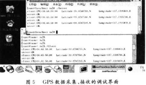
4 Experiments and resultsThe client program that runs the embedded target board collects GPS data and sends it, and the server runs on the host computer to receive the GPS data. Figure 5 shows the data of the debugging interface for GPS data collection and reception. The GPS data received by the monitoring center server is compared with the GPS data collected by the terminal, which realizes wireless, real-time data transmission between the terminal and the monitoring center. The terminal runs stably, the system response time is less than or equal to 3 s, and the data transmission rate reaches 115 200 b/s when the network is good.
5 ConclusionUtilizing the system functions provided by the embedded Linux operating system development platform can simplify multi-task programming, reduce the difficulty of development, and easily complete tasks that are difficult to complete by front and back programming methods. Because CDMA data transmission has many advantages such as being always online, low cost, and being able to switch to SMS mode, ensuring that data transmission is foolproof, and with the development of mobile communication networks, the GPS smart terminal is easier to transition to 3G mobile communication systems smoothly. Therefore, there will be broader application prospects.
a thing that joins together two parts of sth, two vehicles or two pieces of equipment.
Custom Coupling,Coupling Of Encoders,Useful Coupling,Latest Coupling
Yuheng Optics Co., Ltd.(Changchun) , https://www.yhenoptics.com