A parallel bus is a channel through which data is passed between a parallel interface and a computer device. The interface for transferring data between the microcomputer and the external device by means of parallel transmission is called a parallel interface. It has two main features. One is that the binary digits transmitted simultaneously and simultaneously are the data width; the other is between the computer and the peripherals. A responsive communication signal is used to coordinate the data transfer operations of both parties. This contact signal is also known as a handshake signal.
1. Simple parallel interface Simple parallel interface is divided into 0-line handshake parallel interface, 1-wire handshake parallel interface and 2-wire handshake parallel interface.
(1) 0-line handshake parallel interface The so-called 0-line handshake (contact), that is, the interface circuit does not contain the coordination signal for coordinated data transmission, which is the simplest form of the parallel interface, which is divided into the input parallel interface and the output parallel interface. And input/output bidirectional parallel interface in three forms. The 0-line handshake input interface can be directly read by the tri-state gate when the input amount is relatively stable (the input status information does not change within one time, such as the digital input). 0-line handshake output interface When the output digital quantity does not need to be latched, the tri-state gate can be directly output. 0-wire bidirectional input/output interface When a peripheral device and a CPU need to use the data bus to transmit information bidirectionally, the I/O device can transmit information and receive information.
(2) 1-wire handshake parallel interface The 1-wire handshake parallel interface is based on the 0-line handshake parallel interface, and a handshake signal line is added. The 1-wire handshake method always assumes that the data sent by the transmission mode is ready and the receiver can receive it.
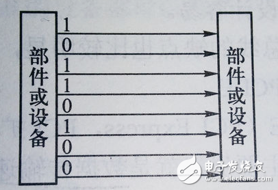
2, programmable parallel interface programmable parallel interface chip types, Intel's 8255A (PPI), Motorola's MC6820 (PIA) and Zilog's Z80-PIO belong to this type of device.
3, computer common parallel bus: STD, PC bus, IEEE488 bus.
(1) PC bus
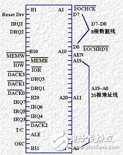
The PC bus is a bus used on IBM PCs and PC/XT machines, also known as XT bus or 8-bit ISA bus. It is not an extension of the CPU pin, formed by the 8282 latch, the 8286 Transceiver, the 8259 Interrupt Controller, the 8237 DMA Controller, and other logic re-drive and combination control, also known as the I/O channel. It has 62 pins, including 8 data lines, 20 address lines, 21 control lines, 2 status lines, and clock, power, and ground lines.
(2) IEEE488 bus
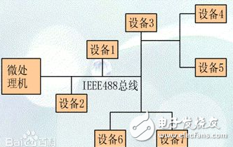
1) Data transfer rate ≤ 1 MB/s.
2) Devices connected to the bus (including the microcomputer as the master) ≤15.
3) The maximum distance between devices is ≤ 20 m.
4) The total cable length of the whole system is ≤220 m. If the cable length exceeds 220 m, the timing relationship will be changed due to the delay, resulting in unreliable operation. In this case, the modem should be attached.
5) All data exchange must be digitized.
6) The bus specification uses a 24-wire combination header and uses negative logic, ie, a logic "1" with a level less than +0.8V; a logic "0" with a level greater than 2V. well
Second, the serial busCommon serial bus for computers: I2C, SPI, RS232, UART, USB
(1) I2C
The I2C bus is a simple, bidirectional two-wire synchronous serial bus developed by Philips. It requires only two wires to transfer information between devices connected to the bus.

The master device is used to initiate the bus transfer of data and generate a clock to open the transferred device, in which case any addressed device is considered a slave device. The relationship between master and slave, transmit and receive on the bus is not constant, but depends on the direction of data transfer at this time. If the host wants to send data to the slave, the master first addresses the slave and then actively sends the data to the slave. Finally, the master terminates the data transfer. If the master wants to receive data from the slave, the master first addresses the slave. The host then receives the data sent by the slave and finally the host terminates the receiving process. under these circumstances. The host is responsible for generating the timing clock and terminating the data transfer.
(2) SPI
SPI is a high-speed, full-duplex, synchronous communication bus that occupies only four wires on the pins of the chip, saving the pins of the chip and saving space for the layout of the PCB. Because of this easy-to-use feature, more and more chips are now integrating this communication protocol, such as the AT91RM9200.
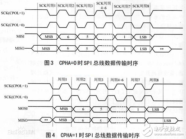
The communication principle of SPI is very simple. It works in master-slave mode. This mode usually has one master device and one or more slave devices. It requires at least 4 wires, and in fact 3 can also be used (in one-way transmission). Also common to all SPI-based devices, they are SDI (data input), SDO (data output), SCLK (clock), CS (chip select).
1) SDI – SerialData In, serial data input;
2) SDO – SerialDataOut, serial data output;
3) SCLK – Serial Clock, clock signal, generated by the master device;
4) CS – Slave enable signal, controlled by the master device.
(3) RS232
RS-232-C is a serial physical interface standard developed by EIA (Electronic Industry AssociaTIon). RS is an abbreviation of the English "recommendation standard", 232 is the identification number, and C is the number of revisions. The RS-232-C bus standard has 25 signal lines, including one main channel and one auxiliary channel.
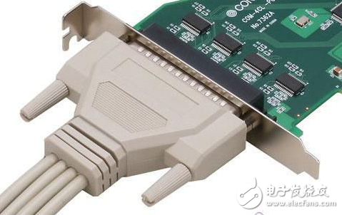
In most cases, the main channel is mainly used. For general duplex communication, only a few signal lines are needed, such as one transmission line, one reception line, and one ground line.
(4) UART
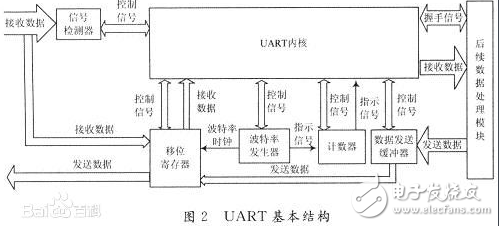
The UART is a general purpose serial data bus for asynchronous communication. The bus bidirectional communication enables full duplex transmission and reception. In embedded design, the UART is used for communication between the host and the auxiliary device, such as communication between the car audio and the external AP, and communication with the PC includes communication with the monitor debugger and other devices such as EEPROM.
(5) USB
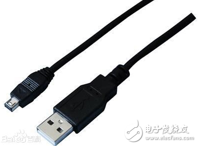
USB, short for English Universal Serial Bus, is an external bus standard that regulates the connection and communication between computers and external devices. It is an interface technology applied in the PC field. The USB interface supports plug-and-play and hot-swap capabilities of the device.
Fork Type Terminals,Insulated Bullet Sockets Terminals,Insulated Bullet Terminals,Type Fork Insulate Terminal
Taixing Longyi Terminals Co.,Ltd. , https://www.longyiterminals.com