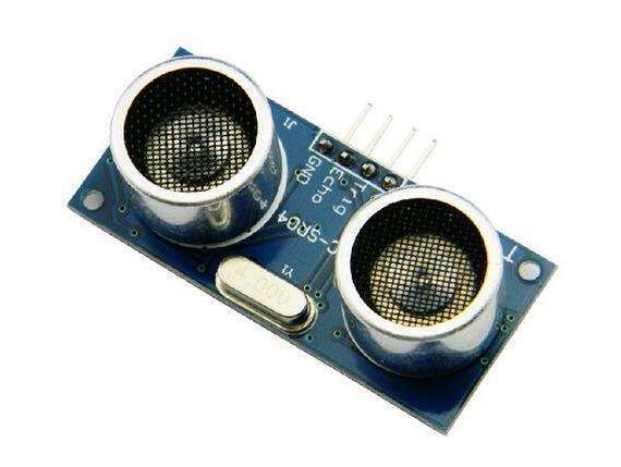
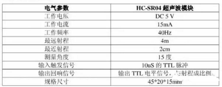
There are many types of ultrasonic ranging modules. The most commonly used URM37 ultrasonic sensors are 232 interfaces by default, which can be adjusted to TTL interface. The URM05 high-power ultrasonic sensor can test distances up to 10 meters, which is considered to be a farther test distance. In addition, there are several SRF series ultrasonic modules that are commonly used abroad. The current ultrasonic module can reach 1cm. This article mainly explains the working principle of HC-SR04 module guitar. Firstly, it introduces the advantages and application fields of HC-SR04 module. Secondly, it explains the working principle and circuit diagram of ultrasonic ranging module. Finally, it introduces electrical parameters, ultrasonic timing diagram, operation and The program, specifically follow the small series to understand.
Advantages and application areas of the HC-SR04 moduleHC-SR04 module advantage
The module has stable performance, accurate measurement distance, high precision module and small blind zone.
Product application areas:
1, robot obstacle avoidance
2, object ranging
3, liquid level detection
4, public security
5, parking lot detection

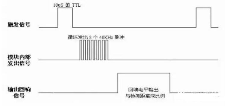
(1) Using IO port TRIG to trigger ranging, giving a high level signal of at least 10us;
(2) The module automatically sends eight 40khz square waves to automatically detect whether there is a signal return;
(3) There is a signal return, and a high level is output through the IO port ECHO, and the high level duration is the time from the transmission to the return of the ultrasonic wave. Test distance = (high time * sound speed (340M / S)) / 2;
(4) This module is easy to use. When a control port sends a high level of 10US or more, it can wait for the high level output at the receiving port. When there is an output, the timer can be turned on. When the port becomes low, the value of the timer can be read. At this time, the time of the ranging can be calculated. With such continuous cycle measurement, you can reach the value of your mobile measurement.
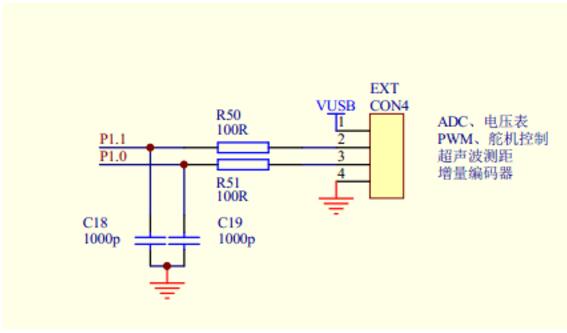
Ultrasonic ranging module circuit diagram
1


Initialize the trig and echo ports are set low, first send a high-level pulse of at least 10 us to the trig (the module automatically sends out 8 40K square waves), then wait, capture the rising edge of the echo output, capture At the same time as the rising edge, the timer is started to start counting, and again waiting to capture the falling edge of echo. When the falling edge is captured, the time of the timer is read. This is the time when the ultrasonic wave runs in the air. According to the test distance = (high level Time* Sound Velocity (340M/S)/2 The distance from the ultrasonic wave to the obstacle can be calculated.
Below is the procedure for Freescale XS128 microcontroller ranging:
While(1)
{
PT1AD0_PT1AD00 = 1; / / input high pulse to the ultrasonic module
PITINTE_PINTE1=1; //Open PIT1 timer
While(!(counter0》=4)); //wait 20us
PITINTE_PINTE1=0; counter0 = 0; / / turn off the timer, the count is cleared
PT1AD0_PT1AD00 = 0; //trig pin is pulled low
PORTB_PB0 = 0; // indicator 0
While(!(PT1AD0_PT1AD01 == 1)); //wait for the rising edge of the echo output
PORTB_PB1 = 0; //Indicator 1
PITINTE_PINTE0=1; //Open the PIT0 timer
While(!(PT1AD0_PT1AD01 == 0)); //waiting for a falling edge
Distance = counter*17/20; //calculate distance, unit CM
PITINTE_PINTE0=0; //turn off the timer
PORTB_PB2 = 0; // indicator 2
PITINTE_PINTE0=1; //Open the timer for 500ms, the digital tube display
While(!(counter)=10000))
{
Showing(distance); //display distance, accurate 1cm
}
PITINTE_PINTE0=0; counter=0; //turn off the timer, clear
}
Freezer Condenser
1. Material: Bundy tube (steel tube coated with copper)
2. Structure: Bundy tubes welded with steel wines
3. Painting: Cathode electrophoretic painting(black)
4. Can produce according to drawing or sample supplied by clients, also can help the clients design and produce different condensers.
Freezer Condenser,Freezer Condenser Unit,Deep Freezer Condenser,Fridge Freezer Condenser
FOSHAN SHUNDE JUNSHENG ELECTRICAL APPLIANCES CO.,LTD. , https://www.junshengcondenser.com