The transformer transformation ratio is defined as the ratio of voltage to current or current, which is the ratio of voltage or current between the primary winding and the secondary winding. In the transformer, the ratio of the primary side electromotive force E1 to the secondary side E2 is called the transformer ratio, and is represented by k, that is, k=E1/E2. The induced potential in the primary winding of the transformer and the secondary winding of the transformer is proportional to the number of turns of the winding. The ratio of the input voltage of the primary winding to the output voltage of the secondary winding is equal to their turns ratio, and the ratio K is called the ratiometric coefficient.
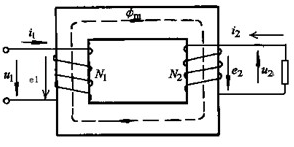
The single-phase transformer has two coils wound together on a closed core. As shown in the figure to the right, the coil connected to the power supply is called the primary coil, and the symbols associated with the primary coil are marked in the lower right corner. With the corner code 1, such as U1, I1, etc., the coil with the load necklace is called the secondary side coil, and the sign of each amount of the correlation amount is marked with the corner code 2 in the lower right corner, such as U2, I2, and the like.

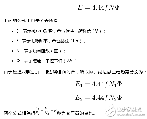
The working principle of the transformer is: when the original winding of the transformer is applied with the alternating voltage u1, an alternating current i1 is generated in the original winding, and this current generates an alternating magnetic flux Φ in the iron core because the primary and secondary windings are in the same On one iron core, when the magnetic flux Φ passes through the secondary winding, an induced electromotive force e2 (ie, a transformer voltage) is generated at the secondary side of the transformer. The magnitude of the induced electromotive force in the transformer is proportional to the number of turns of the coil, the magnitude of the magnetic flux, and the frequency of the power supply.
Primary secondary voltage calculation
The formula for calculating the induced electromotive force in a transformer is:

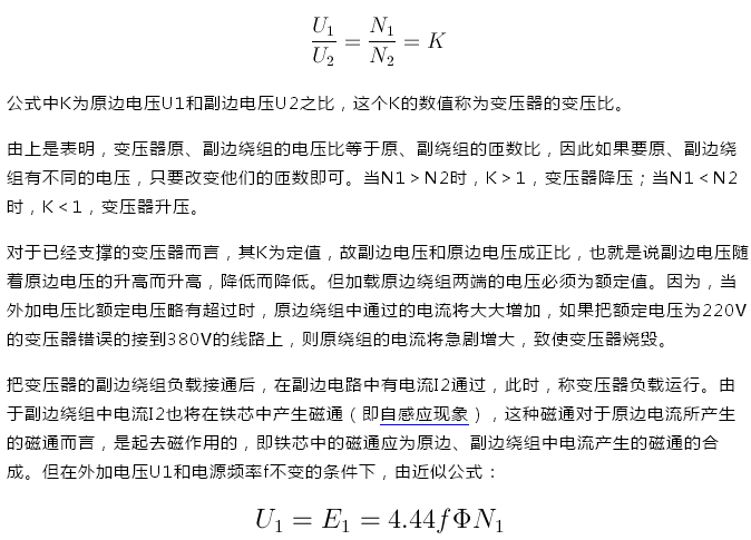
Transformer transformation ratio
In a typical power transformer, the winding resistance voltage drop is small and negligible, so the voltage U1 = E1 can be considered in the primary winding. Since the secondary winding is open, the current I2=0, and its terminal voltage U2 is equal to the induced electromotive force E2, that is, U2=E2. Therefore, the above-mentioned primary and secondary side induced electromotive force formulas are obtained:

It can be seen from the above formula that the synthetic magnetic flux Φ should remain substantially unchanged. Therefore, as I2 appears, the current I1 passing through the primary winding will increase, so that the magnetic flux in the primary winding is prevented from strobing the magnetic flux of the secondary winding, and the other side maintaining the resultant magnetic flux in the core remains unchanged. It can be seen from this that the magnitude of the transformer primary current I1 is determined by the magnitude of the secondary current I2.
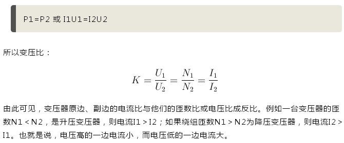
From an energy point of view, the power P1 drawn by the primary winding of the transformer from the power supply should be equal to the output power P2 of the secondary winding (ignoring the coil resistance of the transformer and the transmission loss of the magnetic flux), namely:

Vecsel Module,Laser Module Violet,10 Watt Laser Module,Laser Module Fritzing
AcePhotonics Co.,Ltd. , https://www.cgphotonics.com