Thermostatic soldering iron circuit diagram

The simple constant temperature soldering iron sold in the market, the constant temperature control part is directly powered by the mains to drive the circuit of the two-way thyristor. Once the problem occurs, the components are burnt black or burst, and the color and mark of the damaged device cannot be recognized. Maintenance brings difficulties.
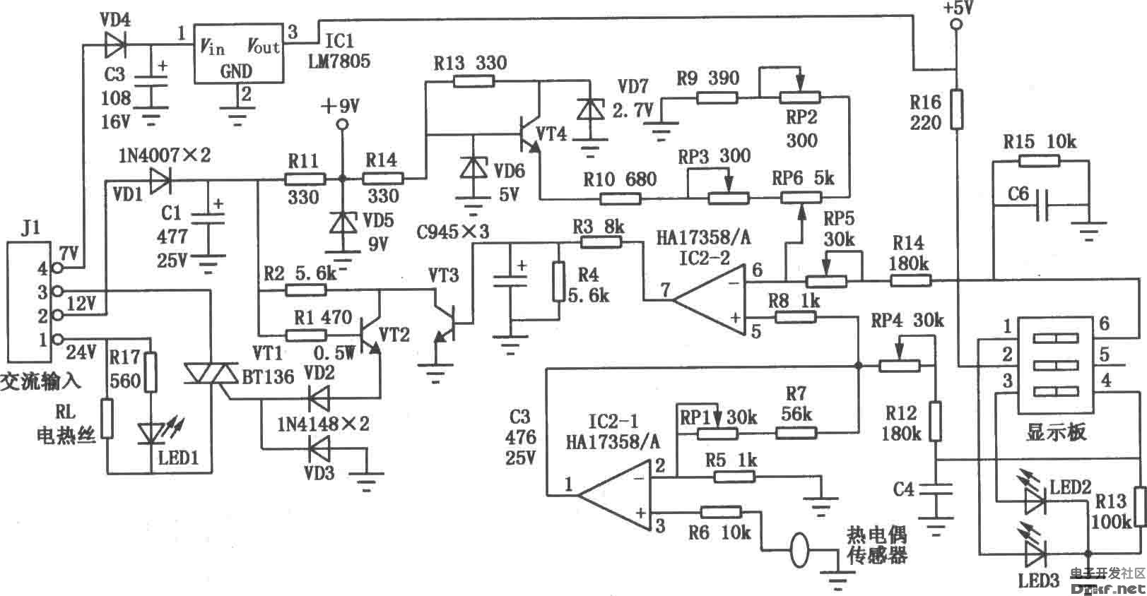
Here, we take the representative Guangzhou Huanghua Electronic Appliance Factory 905C constant temperature electric iron as an example to introduce the working principle of the constant temperature soldering iron.
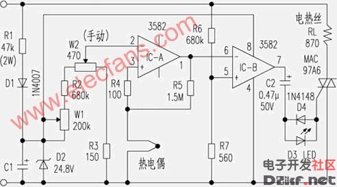
The temperature range of the soldering iron is 100 ° C ~ 400 ° C, the temperature adjustment mark indicates low, medium and high position, the temperature control accuracy is nominally ± 5%, and a thermocouple sensor is used. The control circuit adopts the direct current step-down, filtering and regulated power supply scheme of the AC mains. The working principle is shown in the figure below.
The mains AC220V is used as the power supply voltage and temperature setting voltage source of the comparison device IC after R1 step-down, D1 half-wave rectification, D2 clipping regulation, and C1 filtering. The IC-A3 pin is the thermocouple detection voltage input terminal (corresponding to the temperature value); the 2 pin is the thermostat setting voltage. After the voltages at both ends of pins 2 and 3 are compared, they are output by pin 1. The role of R5 is to feed back a small part of the input to the non-inverting input pin 3, so that the output lock does not change when the small signal fluctuates. When the thermocouple detects that the temperature is low; the level of the 3 pin is lower than the 2 pin, so that the output pin 1 is also low. Further, the IC-B amplifier 6 pin is lowered relative to the fixed bias 5 pin, so that the output 7 pin is high. Since the voltage of the IC-B5 pin is obtained by dividing the AC220V by R6 and R7, the frequency and phase are completely the same as those of the AC220V. After comparing with 6-pin DC, the AC voltage is output at 7 feet. The AC voltage is reversely connected in parallel with C2, D4, D3 and D4 (acting as a bidirectional diode) to trigger the bidirectional thyristor, so that the corresponding voltage is applied to the soldering iron heating wire to achieve the purpose of constant temperature.


The 60W Macbook Charger with MagSafe1 or Magsafe 2 Power Adapter has a magnetic DC connector, so if someone trips on it, the power cord disconnects harmlessly, keeping your MacBook Air safe. It also helps prevent the cable from fraying or weakening over time. Additionally, the magnetic DC helps guide the plug into the system for a quick and safe connection.
60W Apple charger usb c,60w charger macbook air,macbook 60w charger
Shenzhen Waweis Technology Co., Ltd. , https://www.waweis.com