LED driver board PCB: 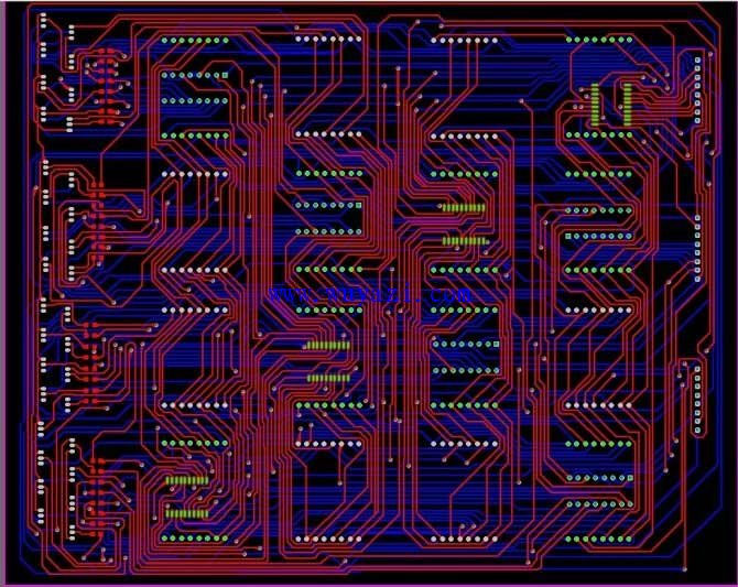
LED driver board schematic: 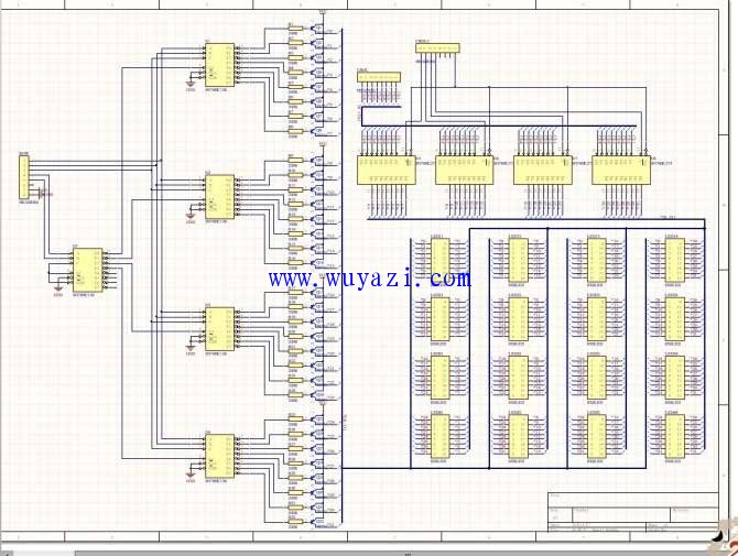
Light pen PCB: 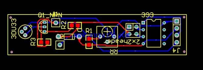
Light pen schematic: 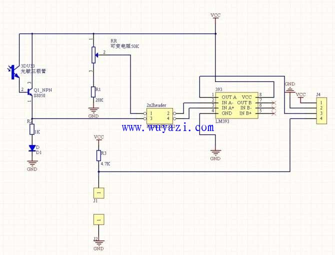
Main control board PCB: 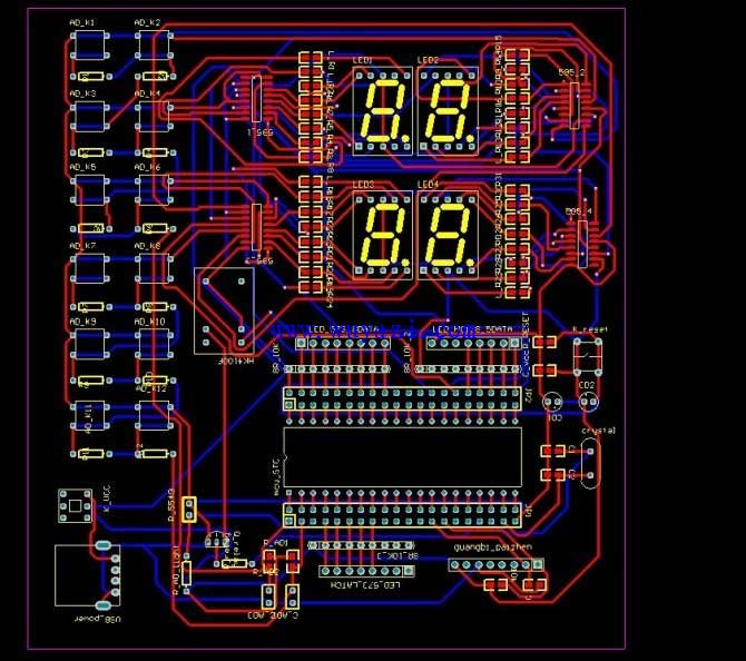
Schematic diagram of the main control board: 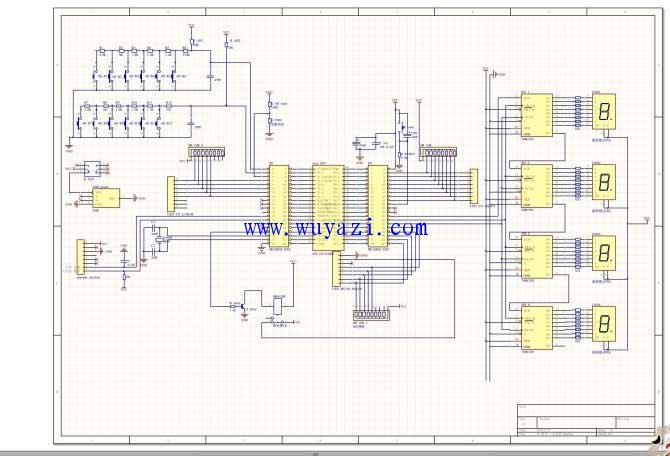
////////////////////////////////////////////////////////////////////////////////////////////// //////////////////////////////////////////////////////////// ///
#include
#define writting 0x01 //Write
#define erasure 0x00 //Erase
#define key_enter 1 //OK
#define key_esc 2 //Exit/Cancel
#define key_words_modle 3 //Multiple words
#define key_light_level 4 //Screen brightness level
#define key_sleep_time 5 //Timeout standby time setting
#define key_fanxian 6 //Reverse operation
#define key_cachu 7 //Erasing operation
#define key_tuoyi 8 //Object drag
#define key_all_screen_del 9 //Full screen erase
#define key_tuoyi_quxiao 10 //The object is dragged and selected after canceling
#define key_crease 11 //Data plus one (standby time, brightness level)
#define key_decrease 12 //Data minus one
//24M crystal oscillator
#define _TH0_TL0_ (65536 - 50000)
#define HI (_TH0_TL0_ / 256) //Assign the upper 8 bits
#define LO (_TH0_TL0_ % 256) //Assign the lower 8 bits
#define M 40 //(2000/50) 1 second to accumulate 50 interrupts
Typedef char (*size)[4]; // Define size as a type that points to the first address of a 32X4 2D array.
Typedef unsigned char uchar;
Extern size point[4];
Extern uchar LED_CODE[5][4];
Extern uchar LED_ROW, LED_LINE;
Extern uchar ROW_TEMP;
Extern uchar KEYS;
Extern uchar li_level;
Extern uchar N;
Extern uchar men_lig;
Extern uchar sleepmin;
Extern uchar min,sec;
Extern uchar xdata LEDDATA0[32][4],LEDDATA1[32][4],LEDDATA2[32][4],LEDDATA3[32][4],LEDDATA4[32][4];
Void LED_GAI(uchar obj_mem[32][4], uchar opera, uchar LED_ROW, uchar LED_LINE );
Void one_word(uchar dat_addr[32][4], uchar caozuo);
Void sys_init();
Void one_word(uchar dat_addr[32][4], uchar caozuo);
Uchar getkey();
Void lightlev(uchar showing[32][4]);
Void sleeptim(uchar showing[32][4]);
Void fanxian(uchar LEDDATA[32][4]);
Void delay_us(int us);
Void LEDcachu(uchar LEDDATA[32][4]);
Void obj_move(uchar led_data[32][4]);
Void fourwords();
Void fou_show();
Void dis_play(uchar show_obj[32][4]);
Void del_all(uchar obj[32][4]);
Void shu_ma_g();
//void daiji();
Void digital_show(uchar row,uchar line);
Void output();
Void input(uchar word);
Void saomiao();
Void light();
//void input(uchar word);;
//////////////////////////////////////////////////////// ////////////////////////////////////////////////////////////
/////////////////////////////////////// file main.c/////////// //////////////////////////////////////////////////////////// ///
//************************************************ *************************
//Works: LED writing dot matrix display
// Author: Chen Yuxi Huang Xiaoguang Tang Minjian
//Time: 2010/04~2010/05
/ / Main controller: IAP12C5A62S2 (STC12 series)
//Crystal: 24MHZ
/ / Functional module analysis:
// The system has 4 function modules:
// 1, light up and draw bright (ie writing function, boot default)
// 2, multi-word continuous writing
// 3, automatic dimming function
// 4, timeout standby function
// And the operations on the above functions are:
// 1, reverse display (can be operated for function 1 and function 2 modules)
// 2, full screen erase (can be operated for function 1 and function 2 module)
// 3, light pen erase (can be operated for function 1 and function 2 module)
// 4, object drag (can be operated for function 1 and function 2 modules)
// 5, writing storage (can be operated for function 1 and function 2 modules) PS: due to time issues,
// And this feature topic is not required, temporarily put on hold
// 6, automatic dimming parameter setting, that is, adjust the brightness level of the user's favorite screen.
// At the same time, the system will automatically dim the LED screen according to the change of ambient light intensity at this level.
// 7, timeout standby time setting
//
//Contact: Tang Minjian (15014225360/)
//
//************************************************ ****************************
#include"myself.h"
#include
#include
Uchar LED_CODE[5][4]= /* The column code of the LED lamp, the code of each LED lamp is 5 bits of data (0 to 2^5), and each time 32 columns of LED lights are synchronized to output 1 bit of data. 5 times. */
{ / * These data are defined in the internal RAM due to the high frequency of operation */
0X00, 0X00, 0XFF, 0XFF,
0X00, 0XFF, 0X00, 0XFF,
0X0F, 0X0F, 0X0F, 0X0F,
0X33, 0X33, 0X33, 0X33,
0X55, 0X55, 0X55, 0X55
};
Uchar LED_ROW, LED_LINE, N; / / store the global variable of the current light pen coordinates, set it to 99 when the system is initialized (any number greater than 32)
Uchar ROW_TEMP; / / "temporary variable" (global variable) of the row coordinates when scanning, in order to enter the interrupt, LED_ROW = ROW_TEMP, save
Uchar KEYS=0; //Store the pressed button number, initialized to 0,
Uchar li_level=10;
Uchar men_lig=10;
Uchar min=0, sec=0;
Uchar sleepmin=5; //Default timeout 5 minutes standby
//sbit pen_key=P3^3; //The light pen button P3^3 is INT0, so the external interrupt is turned off during the initialization phase.
//sbit OUT_EN =P1^7;
Uchar xdata LEDDATA0[32][4],LEDDATA1[32][4],LEDDATA2[32][4],LEDDATA3[32][4],LEDDATA4[32][4];
/ / Store the array of the entire screen data, the screen data volume is 32 / 8 * 32 bytes
Size point[4]; //Array of pointers to two-dimensional arrays
Void delay_us( int us)
{
While(us>0)
{
_nop_();_nop_();_nop_();_nop_();
_nop_();_nop_();_nop_();_nop_();
_nop_();_nop_();_nop_();_nop_();
_nop_();_nop_();_nop_();_nop_();
_nop_();_nop_();_nop_();_nop_();//24 empty operation instructions are 1US, now 20
Us--;
}
}
Void main()
{
Uchar light_T;
N=3;
light_T=0;
Relay=0;
Point[0]=LEDDATA1;point[1]=LEDDATA2;
Point[2]=LEDDATA3;point[3]=LEDDATA4;
//**********************
/ / Timer 1 initialization
TL0 = _TH0_TL0_ % 256;
TH0 = _TH0_TL0_ / 256 + (char) CY;
TR0 = 1;
//*****************
//sys_init(); //System initialization, put the first address of 4 arrays into point[4]
While(1)
{
One_word(LEDDATA0,writting); //Scan a point and display it
KEYS=getkey(); //AD scan button, in fact, the button scan is performed 10 times in 1 second, and it is not necessary to follow this dis_play() to do at least 20 scans.
//Because the human hand cannot be pressed more than 10 times in one second.
/ / If you find that the LED screen responds slowly to the light pen during debugging, you need to modify the time ratio of getkey() in one second.
// This also means the number of executions of getkey() in one second. This can be done: set a counter, +1 for each dis_play(), initial value
// is 0. When it is 1, it is cleared, and get_key() is called. Otherwise, get_key() is not executed.
If(KEYS) //getkey() detects the value of the button when the button is pressed, and returns 0 if no button is pressed.
{
Switch(KEYS)
{
Case key_enter : break; //"determine" meaningless here
Case key_esc : break; //No exit, it is already the bottom layer
Case key_words_modle : fourwords();break; //Enter multi-word continuous write function
Case key_light_level : lightlev(LEDDATA0);break; //Adjust the parameters of the screen brightness level
Case key_sleep_time : sleeptim(LEDDATA0);break; //Adjust the timeout for timeout standby
Case key_fanxian : fanxian(LEDDATA0);break; //anti-display operation
Case key_cachu : LEDcachu(LEDDATA0);break; //Erasing operation
Case key_tuoyi : obj_move(LEDDATA0);break; //object drag
Case key_all_screen_del : del_all(LEDDATA0);break; //
Case key_tuoyi_quxiao : break; //" cancel after selecting the object to confirm "nothing here
Case key_crease : break; //"data+1" doesn't make sense here
Case key_decrease : break; //"data-1" doesn't make sense here
Default : break; //If there is no key match, exit directly. Although it does not happen here, it is safe to add
}
}
KEYS=0;
light_T++;
If(light_T>5){light_T=0;light();} //Automatically dim 4 times in one second
}
}
Void one_word(uchar dat_addr[32][4], uchar caozuo) // Part of a second, about 1/20th of a second. Perform a point scan and display it on the LED screen.
//And update the display of the digital tube
{
If(!pen_key)
{ saomiao (); / / The button on the light pen is pressed to scan, the light pen here accounted for a large head, 3DU33
/ / Response time insurance point to calculate about 5uS delay. In this way, each scan is required when it is worst.
//The length is: T=(5+5)*32*N+(5+5)*N=330N(uS).N is the high->low transition number for 32 columns of LEDs, and also
//The number of times the counter has overflowed.
LED_GAI(dat_addr, caozuo, LED_ROW, LED_LINE); //Modify the current screen data content so that the update is displayed below. Wrating means LED_GAI() function
// Operate "and 0" on the LED_LINE%8 bit data in LEDDATA1[LED_ROW][LED_LINE/8].
/ / Because the 74HC595 output port low level corresponds to the strobe column.
// On the contrary, if the parameter is erasure, then the same bit of data is "or 1"
// In addition, if pen_key is not pressed, the data is not updated and there is no need to change it.
}
Else
{LED_ROW=99;LED_LINE=99;} //When the button on the stylus is not pressed, ie the user does not intend to write, the current coordinate value of the stylus is displayed as 99,99.
Shu_ma_g(); // Digital tube update static display
Dis_play(dat_addr); //LED update display, no matter whether the scan is executed or not, the LED screen must be displayed, taking up time, and it takes most of the CPU.
/ / so that the human eye does not notice the flicker, if the display length ratio is not >> scan time ratio, then the human eye will feel the LED is flashing or slightly scanning
//("No highlights") is too bright and the display content ("bright spots") is not bright enough
/ / Mainly this function allocates time to achieve at least 20 scans in 1 second.
}
Void LED_GAI(uchar obj_mem[32][4], uchar opera, uchar LED_ROW, uchar LED_LINE )
{uchar temp,byteline,bitline;
Byteline=(LED_LINE-1)/8, bitline=(LED_LINE-1)%8;
If (opera) / / write, that is, the corresponding bit is "with 0" operation
{
Temp=0X80;
Temp=_cror_(temp,bitline);
Obj_mem[LED_ROW][byteline]=obj_mem[LED_ROW][byteline]|temp;
}
Else{
Temp=0x7F;
Temp=_cror_(temp,bitline);
Obj_mem[LED_ROW][byteline]=obj_mem[LED_ROW][byteline]&temp;
}
}
Void Timer1() interrupt 3
{
Static unsigned char count = 0; //Define the static variable count
TR0 = 0; //The following adjusts the time error of stacking onto the stack
TL0 += (_TH0_TL0_ + 9) % 256;
TH0 += (_TH0_TL0_ + 9) / 256 + (char)CY;
TR0 = 1;
Count++;
If(pen_key)
If(KEYS==0)
{
Sec=0;
Min=0;} //The light pen is not used, and any button is not pressed
Else{ if(count >= 20)//1 second time to
{
Count = 0;
Sec++;
If(sec == 60)//1 minute time to
{
Min++;
Sec = 0;
}
}
If(min>=sleepmin) relay=1;//off screen
}
}
//////////////////////////////////////////////////////// //////////////////////////////////////////////////////////// ////////////
///////////////////////////////////////// file/automatic dimming.c///////// //////////////////////////////////////////////////////////// /////
#include"myself.h"
#include
#include
Void light()
{
Uchar finish, adc_result;
//*********************
//ADC_POWER_ON
ADC_CONTER|=0X80;
Delay_us(1000); //1ms delay
//*********************
//*********************
/ / Select the analog port (P1.2), that is, disconnect the pull-up resistor to form an analog port
P1ASF=0x04;
//*********************
//*********************
/ / Select P1.2 as the ADC conversion channel
ADC_CONTER&=0XF0; //low three bits clear
_nop_();_nop_();_nop_();_nop_();//Let ADC_CONTER data stabilize
ADC_CONTER|=0X03; //Switch channel
Delay_us(20); //delay 20us to stabilize the voltage
//*********************
//*********************
/ / Take the AD conversion result, ADRJ power-on reset defaults to 0, that is, take high 8-bit data
ADC_RES=0XFF; // initialized to 0XFF;
ADC_CONTER|=0X08; //ADC_START
_nop_();_nop_();_nop_();_nop_();
Do{
Finish=0X10; //0001 0000(b)
Finish|=ADC_CONTER;
}while(finish); //wait for AD conversion to complete
ADC_CONTER&=0XE7; //11100111, clear ADC_FLAG and ADC_START, stop AD conversion
Adc_result=ADC_RES;
//*********************
If(adc_result>0x80)li_level=10; //R5549 resistance is above 100K
Else if(adc_result>0X71)li_level=9; //R5549 resistance is in the range of 80K~100K
Else if(adc_result>0x60)li_level=8; //R5549 resistance is in the range of 60K~80K
Else if(adc_result>0X49)li_level=7; //R5549 resistance is in the range of 40K~60K
Else if(adc_result>0X2A)li_level=6; //R5549 resistance is in the range of 20K~40K
Else if(adc_result>0X17)li_level=5; //R5549 resistance is in the range of 10K~20K
Else li_level=4; //down to level 4
}
Void lightlev(uchar showing[32][4])
{
Uchar key;
Uchar save_row=LED_ROW, save_line=LED_LINE; //Use to save digital tube data
While(1)
{
Key=getkey();
Switch(key)
{
Case key_esc : return;break; //exit
Case key_crease : if(men_lig4) men_lig--;break; //"data-1" minimum value is 4
Default : break; //If there is no key match, exit directly. Although it does not happen here, it is safe to add
}
LED_ROW=0x00; LED_LINE=men_lig;
Shu_ma_g();
Dis_play(showing);
LED_ROW=save_row;LED_LINE=save_line;
}
}
//////////////////////////////////////////////////////// //////////////////////////////////////////////////////////// ////////////
//////////////////////////////////////// file button scan. c////////// //////////////////////////////////////////////////////////
#include"myself.h"
#include
#include
Uchar getkey()
{
Uchar key, finish, adc_result;
//*********************
//ADC_POWER_ON
ADC_CONTER|=0X80;
Delay_us(1000); //1ms delay
//*********************
//*********************
/ / Select the analog port (P1.0, P1.1), that is, disconnect the pull-up resistor to form an open-drain output
P1ASF=0x03;
//*********************
//*********************
/ / Select P1.0 as the ADC conversion channel
ADC_CONTER&=0XF8; //The lower three positions are zero, and P1.0 is selected at the same time.
_nop_();_nop_();_nop_();_nop_();//Let ADC_CONTER data stabilize
Delay_us(20); //delay 20us to stabilize the voltage
//*********************
//*********************
/ / Take the AD conversion result, ADRJ power-on reset defaults to 0, that is, take high 8-bit data
ADC_RES=0XFF; // initialized to 0XFF;
ADC_CONTER|=0X08; //ADC_START
_nop_();_nop_();_nop_();_nop_();
Do{
Finish=0X10; //0001 0000(b)
Finish=ADC_CONTER&finish;
}while(!finish);
ADC_CONTER&=0XE7; //11100111, please AD conversion completion flag, stop AD conversion
Adc_result=ADC_RES;
//*********************
If (adc_result0x99)key=7; //>3v
Else if(adc_result>0X80)key=6; //>2.5v
Else if(adc_result>0X66)key=5; //>2V
Else if(adc_result>0X4C)key=4; //>1.5V
Else if(adc_result>0X33)key=3; //>1V
Else if(adc_result>0X19)key=2; //>0.5V
Else key=1;
}else{
//*********************
//ADC_POWER_ON
ADC_CONTER|=0X80;
Delay_us(1000); //1ms delay
//*********************
//*********************
/ / Select the analog port (P1.0, P1.1), that is, disconnect the pull-up resistor to form an open-drain output
P1ASF=0x03;
//*********************
//*********************
/ / Select P1.0 as the ADC conversion channel
ADC_CONTER&=0XF8; //low three bits clear
_nop_();_nop_();_nop_();_nop_();//Let ADC_CONTER data stabilize
ADC_CONTER|=0X01;
Delay_us(20); //Switch the channel, delay 20us to stabilize the voltage
//*********************
//*********************
/ / Take the AD conversion result, ADRJ power-on reset defaults to 0, that is, take high 8-bit data
ADC_RES=0XFF; // initialized to 0XFF;
ADC_CONTER|=0X08; //ADC_START
_nop_();_nop_();_nop_();_nop_();
Do{
Finish=0X10; //0001 0000(b)
Finish|=ADC_CONTER;
}while(finish); //wait for AD conversion to complete
ADC_CONTER&=0XE7; //11100111, please AD conversion completion flag, stop AD conversion
Adc_result=ADC_RES;
//*********************
If (adc_result0x99)key=14; //>3v
Else if(adc_result>0X80)key=13; //>2.5v
Else if(adc_result>0X66)key=12; //>2V
Else if(adc_result>0X4C)key=11; //>1.5V
Else if(adc_result>0X33)key=10; //>1V
Else if(adc_result>0X19)key=9; //>0.5V
Else key=8;
}
}
Return key;
}
//////////////////////////////////////////////////////// //////////////////////////////////////////////////////////// ////////////
/////////////////////////////////////// file timeout standby.c/////////// /////////////////////////////////////////////////////////
#include"myself.h"
#include
#include
Void sleeptim(size showing)
{
Uchar key;
Uchar save_row=LED_ROW, save_line=LED_LINE; //Use to save digital tube data
While(1)
{
Key=getkey();
Switch(key)
{
Case key_esc : return;break; //exit
Case key_crease : if(sleepmin1)sleepmin--;break; //"data-1" minimum value is 1
Default : break; //If there is no key match, exit directly. Although it does not happen here, it is safe to add
}
LED_ROW=0x00; LED_LINE=sleepmin;
Shu_ma_g();
Dis_play(showing);
LED_ROW=save_row;LED_LINE=save_line;
}
}
//////////////////////////////////////////////////////// //////////////////////////////////////////////////////////// ////////////
//////////////////////////////////////// file digital tube display. c///////// //////////////////////////////////////////////////////////// ////////
#include "myself.h"
#include
#include
Sbit RCLK_595=P2^5;
Sbit SRCLK_595=P2^6;
Sbit SER_595=P2^7;
Void shu_ma_g()
{
Digital_show(LED_ROW,LED_LINE);
}
Void digital_show(uchar row,uchar line)
{
Uchar one;
One=line%10;
Input(one);
_nop_();_nop_();
One=(line-one)/10;
Input(one);
_nop_();_nop_();
One=row%10;
Input(one);
_nop_();_nop_();
One=(row-one)/10;
Input(one);
_nop_();_nop_();
Output();
}
/ / Latch the data in the shift register to the output register and display
Void output()
{
RCLK_595=0;
_nop_();_nop_();
RCLK_595=1;
_nop_();_nop_();
RCLK_595=0;
}
//;***** shift register receives a byte (eg 3FH) data subroutine
Void input(uchar word)
{
Uchar i;
Word=~word; //Common yang, first counter
For(i=0;i
#include
Void dis_play(uchar show_obj[32][4])
{
Uchar row, line, temp_row, templine;
For(row=0;row
#include
Void fourwords()
{
Uchar count;
For(count=0;count=key_words_modle&&KEYS
#include
Void saomiao()
{
Uchar tempsave, mod_save;
Uchar N_times;
TR1=0;//off timer 1
OUT_EN=1; //First let the lock LED dot matrix display
Mod_save&=0XF0;
TMOD|=0X06; //TMOD=XXXX 0110, counter, eight-bit auto-reload
TH0=0XFF-N;
TL0=0XFF-N;
TR0=1; //Start the calculation of the external negative transition pulse, at this time OUT_EN is still the lock output
For(ROW_TEMP=0;ROW_TEMP
#include
#define CLICK P3^3
#define X LED_ROW
#define Y LED_LINE
Void enkey(uchar led_data[32][4], uchar x, uchar y); //Invert the xth row and the yth column
Void mov(uchar a,uchar b,uchar c,uchar d);//a^b->c^d
Void obj_move(uchar led_data[32][4])
{
Struct zuobiao
{
Uchar x,y;
}start,end,go,pref;
Uchar temp,i,j,chang,kuan;
Uchar xdata save[32][4];
Uchar xdata tempscr[32][4];
While(CLICK);//waiting to press
Saomiao();
Start.x=X;start.y=Y;//starting point
While(!CLICK);//waiting to bounce
Saomiao();
End.x=X;end.y=Y;//end point
If(start.x>=end.x){temp=start.x;start.x=end.x;end.x=temp;} //Locate start to the top left corner of the rectangle,
If(start.y>=end.y){temp=start.y;start.y=end.y;end.y=temp;} //end to the bottom right corner
For(i=start.x;i=start.x&&X=start.y&&Yc^d
{
Uchar ta,tb;
Ta=0x80; tb=0x7f;
Ta=_cror_(ta,b);tb=_cror_(tb,d);
Ta=a&ta;tb=b&tb;
If(b>d)ta=_crol_(ta,bd);
Else ta=_cror_(ta,db);
c=ta|tb;
}
/////////////////////////////////////// file operating.c///////////// //////////////////////////////////////////////////////
#include"myself.h"
#include
#include
Void fanxian(uchar LEDDATA[32][4])
{
Uchar row;
For(row=0;row<32;row++)
{
LEDDATA[row][0]=~LEDDATA[row][0];
LEDDATA[row][1]=~LEDDATA[row][1];
LEDDATA[row][2]=~LEDDATA[row][2];
LEDDATA[row][3]=~LEDDATA[row][3];
}
}
Void LEDcachu(uchar LEDDATA[32][4])
{
Do
{
One_word(LEDDATA,erasure); //Scan a point and display it
KEYS=getkey(); //AD scan button, in fact, the button scan is performed 10 times in 1 second, and it is not necessary to follow this dis_play() to do at least 20 scans.
//Because the human hand cannot be pressed more than 10 times in one second.
/ / If you find that the LED screen responds slowly to the light pen during debugging, you need to modify the time ratio of getkey() in one second.
// This also means the number of executions of getkey() in one second. This can be done: set a counter, +1 for each dis_play(), initial value
// is 0. When it is 1, it is cleared, and get_key() is called. Otherwise, get_key() is not executed.
/*if(KEYS) //getkey() detects the value of the button when the button is pressed, and returns 0 if no button is pressed.
{
Switch(KEYS)
{ //In order not to make users feel confused, multi-level nesting is not allowed here, so
/ / Many of the following are not allowed
Case key_enter : break; //"determine" meaningless here
Case key_esc : return; break; // exit, return to light and draw mode
Case key_words_modle : break; //Do not allow multi-word continuous writing in this mode
Case key_light_level : break; / / does not allow adjustment of the screen brightness level parameters
Case key_sleep_time : break; //Do not allow adjustment of timeout for timeout standby
Case key_fanxian : break; //Do not allow reverse operation
Case key_cachu : break; //Do not allow erase operation
Case key_tuoyi : break; //Do not allow objects to be dragged
Case key_tuoyi_xuanding : break; //"object selection confirmation "no meaning here
Case key_tuoyi_quxiao : break; //" cancel after selecting the object to confirm "nothing here
Case key_crease : break; //"data+1" doesn't make sense here
Case key_decrease : break; //"data-1" doesn't make sense here
Default : break; //If there is no key match, exit directly. Although it does not happen here, it is safe to add
}
}
*/ //This paragraph is not needed
}while(KEYS!=key_esc);
}
Void del_all(uchar obj[32][4])
{
Uchar row;
For(row=0;row<32;row++)
{
Obj[row][0]=0X00;
Obj[row][1]=0X00;
Obj[row][2]=0X00;
Obj[row][3]=0X00;
}
}
//////////////////////////////////////////////////////// //////////////////////////////////////////////////////////// ////////////
Axial Fan,Axial Flow Fan,Axial Blower,Axial Exhaust Fan
Hangzhou Jinjiu Electric Appliance Co Ltd. , https://www.jinjiufanmotor.com