1 Introduction
Since the application of bus communication technology in automobiles in the 1980s [1], it has developed rapidly under the promotion of electronic technology and automotive technology. At present, a variety of automotive bus standards have been formed for different occasions, such as MOST, CAN. , TTP, LIN, etc. The communication nodes and data traffic in the automobile bus continue to increase, and the nodes are increasingly complex, which makes the bus bus face difficulties in terms of weight, layout, cost, communication efficiency, etc. The way out of this dilemma lies in the implementation of the network and hierarchical system of the bus. Class A bus - Local Interconnect Network (LIN) has emerged. LIN is a structure
A new low-speed serial bus that is simple, flexible, and inexpensive, and is mainly used as an auxiliary network or sub-network for high-speed buses such as CAN. In the case of low bandwidth requirements, simple functions, and low real-time requirements, such as the control of body appliances, the use of LIN bus can effectively simplify the network harness, reduce costs, and improve network communication efficiency and reliability.
2, car network
At present, there are various vehicle bus standards for different occasions such as engine and chassis control, body electrical control, and vehicle multimedia. SAE (Society of Automotive Engineering) divides the automotive network bus into three categories according to the transmission speed, as shown in Table 1.
Table 1 Automotive Network Classification 
There are many types of Class A bus protocols, but for a long time no protocol has become a common standard in the field. In 1998, Audi, Motorola, BMW, DaimlerChrysler, VCT, Volvo and Volkswagen jointly established the LIN Association. Based on the research of the Class A bus, a new Class A bus, LIN, was proposed. Its low cost and excellent performance are widely accepted by major manufacturers and are expected to become the international standard for Class A buses.
3, LIN
The LIN bus is based on the SCI/UART data format and uses a single-master multi-slave mode. The bus consists of only three wires (power, ground, and data lines). The LIN bus driver/receiver specification complies with the ISO9141 standard and has EMI performance. improve. LIN guarantees network node interoperability in hardware and software and predicts EMC.
The main features of LIN: low cost, based on the general UART/SCI interface, almost all microcontrollers have the necessary hardware for LIN; very few signal lines can achieve ISO9141 standard; transmission rate up to 20Kb / s, maximum bus length 40m; single-master/multi-slave mode, no bus arbitration; slave node can realize self-synchronization without quartz or ceramic oscillator; guarantee delay time of signal transmission; no need to change hardware and software of LIN slave node Add or remove nodes, etc. on the network.
The initial version of the LIN bus specification, LIN 1.0, was released by the LIN Association in July 1999 and has since been revised. The current version is LIN 2.0, which was released by the LIN Association in September 2003. The LIN specification includes a transport protocol specification, a transport medium, a development tool interface, and a software programming interface. The standardization of LIN will change the current situation of low-end automotive network clutter and will reduce the development, production, service and maintenance costs of automotive electronic equipment.
3, 1LIN topology
LIN uses a single-master multi-slave mode. A LIN network consists of a host node and several slave nodes.
(Because too many nodes will cause the network impedance to be too low, the total number of nodes in a LIN network should not exceed 16.) The host node includes both the host task and the slave task, and the slave node only includes the slave task, as shown in Figure 1. . The host node can also be connected via a gateway to other buses such as CAN. 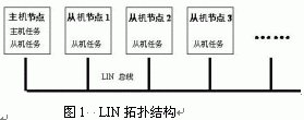
3, 2LIN data transmission
The data in the LIN bus is transmitted by means of a message frame, which consists of a message header and a response.
The header can only be sent by the host task, which includes the synchronous interval field, the synchronization field and the identifier field. The sync interval field is at least 13 consecutive dominant bits (low level) that mark the beginning of a message frame. It is followed by a synchronous field, and the synchronous field logic value is 0x55. The slave node uses the synchronous field to synchronize with the host node. The identifier field follows the sync field and is one byte in length. The lower 6 bits of the identifier field are identifier bits, which can form 64 identifiers, 60 of which are used for general message transmission, two for diagnostic frames, one for user-defined frames, and one for LIN extension. . The last two digits of the identifier are parity bits.
The identifier indicates the content of the current frame, and the slave node determines from this whether it should respond to the current frame and respond to it.
The response is sent by the slave task, which consists of the data field and the checksum field. The data field consists of data carried in a message frame and is one to eight bytes in length. The end of the message frame is the checksum field, which is one byte long. The LIN1.3 and its previous specification versions specify that the checksum field only verifies the data field, called the traditional checksum, LIN2.0. The specification specifies that the checksum field check range includes the data field and the identifier field, called the enhanced checksum.
A complete message frame is shown in Figure 2. 
Figure 2 LIN message frame
According to different transmission conditions, message frames can be divided into absolute frame, trigger frame, discrete frame, diagnostic frame, user-defined frame and reserved frame [2]. All communication on the LIN bus is initiated by the host task in the host node. The host task determines the current communication content according to the schedule, sends the corresponding frame header, and allocates a frame channel for the message frame. After the slave node on the bus receives the frame header, it interprets the identifier to determine if it should respond to the current communication and what response it should make. Based on this message filtering method, LIN can implement multiple data transmission modes, and one message frame can be received and utilized by multiple nodes at the same time, as shown in FIG. 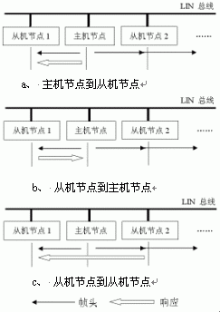
Figure 3 LIN data transmission mode
3.3 bus sleep and wake up
When necessary, the host node can send a diagnostic frame with the identifier 0x3C and the first byte of the data field to 0 to put all the slave nodes into sleep state. If the bus does not have any activity for more than 4 seconds, the slave node also automatically enters. Sleep state to reduce power consumption.
Any node in the sleeping LIN network can request a wake-up bus. All nodes on the bus should be out of sleep and ready to receive bus commands after receiving a wake-up request. The host node is also woken up after receiving the wakeup request, and sends the frame header after the slave node is ready to find the cause of the wakeup.
3.4 Error detection and processing
The LIN specification defines six different types of message errors: bit errors, checksum errors, identifier errors, slave non-responsive errors, bus inactivity errors, and sync field inconsistencies. The host node and the slave node detect several of these six errors, respectively.
4. LIN application design
LIN is a low-speed serial bus that is proposed for automotive applications and is mainly used in automotive electronic control systems to enable the connection of smart sensors, actuators, and the like. LIN is positioned in the lower local network on the car. Steam formed by CAN 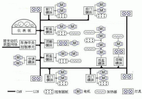
Figure 4 is based on CAN/LIN hierarchical automotive network
The upper trunk network of the car, and in the case where high speed and versatility of CAN are not required, the lower layer local network is formed by LIN, and the hierarchical network structure is realized, so as to achieve reasonable distribution and utilization of network resources, and convenient and flexible arrangement of lines. The purpose of reducing costs. A typical CAN-LIN bus based hierarchical car body network is shown in Figure 4.
Now take the door LIN network as an example to introduce the general method of LIN bus design.
The structure of the door control LIN network and its arrangement on the door are as shown in Fig. 5. The network consists of a host node, a rear view mirror slave node, a window shaker slave node, and a door lock slave node. 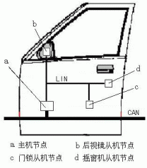
Figure 5 door control LIN network
The host node collects the status of each local control switch and accepts the remote information on the CAN bus, generates a control command according to this, and converts the command into a LIN message frame and sends it to the corresponding slave node through the LIN network, and the slave node receives the self. After the relevant message frame, the message frame is unpacked and interpreted, and then the corresponding actuator action is controlled according to the obtained instruction, thereby realizing the control of each component of the door. At the same time, the slave node feeds back the status of its control component to the host node when needed, and the host node provides the status information to the driver through the indicator light or the horn or sends it to other control units via the CAN bus. The host node also acts as a gateway for the LIN network to connect to the upper CAN network.
Figure 6 is a block diagram showing the structure of the host node and the rear view mirror slave node of the door control LIN network. The host node is mainly composed of a controller, a power supply, a control button, a LIN interface, a CAN interface, and an indicator light. The rear view mirror slave node is mainly composed of a controller, a power supply, a LIN interface, an actuator drive unit, and an actuator such as a rearview mirror adjustment motor and a defrosting heater. 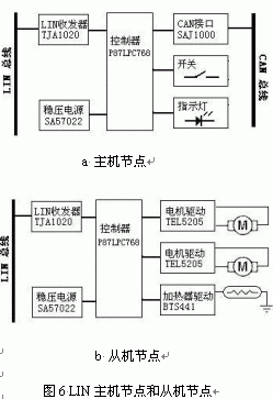
Both the host node and the slave node controller adopt PHILIPS high-performance 8-bit single-chip microcomputer P87LPC768. In addition to the typical functions of the 51 series single-chip microcomputer, the single-chip microcomputer fully meets the hardware requirements of the LIN controller, and also has an on-chip watchdog and oscillator. Modules can effectively simplify the structure of the LIN node and reduce costs. The LIN transceiver uses the TJA1020 manufactured by PHILIPS. Its available baud rate range is 2.4-20Kbits/s. It has high immunity to electromagnetic interference (EMI) and can automatically trim the output waveform to reduce electromagnetic radiation (EME). At rates below 10 Kb/s, the TJA1020 can operate in a low slope mode to further reduce electromagnetic emissions. The power module is mainly composed of the voltage regulator SA57022 produced by PHILIPS. The SA57022 can be turned on or off through the ON/OFF pin. It cooperates with the LIN transceiver to achieve sleep and wake-up of the node. The CAN interface of the host node consists of a CAN controller SAJ1000 and a CAN driver 82C250. In the slave node, a semiconductor power switching device such as BTS432 is used to replace the conventional relay as a switching device of each actuator, which has the advantages of quick response, high reliability, compact structure, and the like, and the load state can be diagnosed through the feedback pin.
5, the conclusion
With the development of automotive technology and network communication technology, the network of automotive information communication is an inevitable trend. The diversification of automotive information communication has promoted the emergence and development of automotive hierarchical networks. As a new type A bus with excellent performance and low price, LIN will further promote the implementation and improvement of the automotive hierarchical network structure and promote the development of automotive technology. At the same time, LIN, as an open protocol, has broad application prospects in the industrial and home appliance fields.
This article refers to the address: http://
Mineral Insulated Cable,Copper Mineral Insulation Cable,Copper Core Copper Sheath Cable,Fire Resistant Cable
Baosheng Science&Technology Innovation Co.,Ltd , https://www.cablebaosheng.com