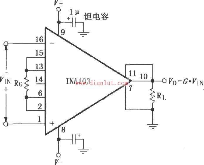
 The following is the circuit diagram of [Application Connection Circuit of INA103]
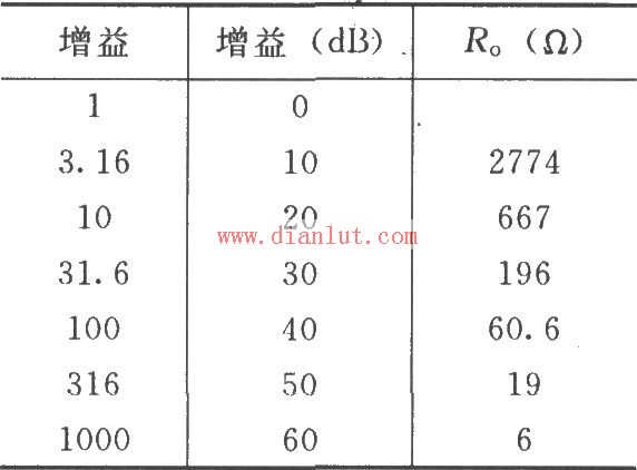
As shown in the figure, the power supply terminal of the chip should be filtered with a 1μF tantalum capacitor and placed as close as possible to the power supply pin of the chip. The output detection terminal (11-pin) and the output reference terminal 7 must be connected with low resistance. In the connection path, even if there is a very small resistance, the amplifier's common mode rejection ratio will be lowered. In order to avoid self-excitation of the amplifier, the leads should be as short as possible, and the gain setting resistor and gain detection are directly connected to the chip pins. The choice of gain is shown in the table below.
 (Editor: Circuit Diagram)
 3000W Digital Tv Transmitter,3Kw Analog Tv Transmitter,3Kw Vhf Tv Transmitter,Single Channel Tv Transmitter
Anshan Yuexing Technology Electronics Co., LTD , https://www.yxhtfmtv.com