ASIC designs continue to grow in size and complexity, and new advances in the capacity and performance of modern FPGAs mean that two-thirds of these designs can be modeled using a single FPGA. However, one-third of these designs remain (that is, 1/9 of all ASIC designs) require a prototype board based on multiple FPGAs.
In the not too distant past, for ASIC design teams, the primary solution in such cases was to build their own custom prototype boards for multiple FPGAs. However, today, using off-the-shelf multiple FPGA prototyping boards—for example, development boards from Synplicity's prototyping partners—can be combined with the right design tools to save weeks, otherwise it will take months Verification time and tens of thousands of dollars spent on NRE fees.
This article first discusses the main techniques that ASIC verification can use. Next, the article considers the advantages and disadvantages of building a custom multiple FPGA prototyping board compared to using an off-the-shelf product. Finally, the paper introduces the most advanced segmentation and synthesis design tools used to validate large designs, using internally developed or off-the-shelf prototype boards for multiple FPGAs.
Alternative verification technology
Today's high-end ASICs, such as those used in cell phones, communications, graphics subsystems, and signal processing applications, often contain multiple CPU and DSP cores that combine hardware accelerators, peripherals, interfaces, and memory management cores. (For the purposes of these discussions, the term ASIC is assumed to include ASSP and SoC devices.) Therefore, in order to meet the market needs of the chip, develop, port, integrate, debug, and verify the contents of any embedded software as early as possible during the design phase. .
ASIC's RTL full-featured verification—and its own embedded software—is one of the most time-consuming and difficult parts of the ASIC design process. Statistics show that 70% of today's ASIC designs require rework. In addition to being extremely expensive, rework can cause the project to lose its market space, which will seriously damage the company's reputation and financial bottom line.
The three main verification options open to ASIC designers are simulation, simulation, and FPGA prototyping.
*Simulation: Software-based simulation is widely used, but even when running on a truly high-end (and relatively expensive) computer platform, it runs six to ten orders of magnitude slower than the actual ASIC hardware, making it a A technology that takes a lot of time and is extremely inefficient. In order to provide an understanding of the size of the entire system, software simulation can typically reach speeds of just a few Hz (that is, the designed system clock is a few cycles per second relative to the real time). In fact, this means that a wide range of software verifications can be implemented in just a small part of the design.
*Simulation: Hardware-based simulation is another option, but it is still at least three orders of magnitude slower than actual ASIC hardware, because a large number of related multiplexing techniques slow down the verification speed to just 500 KHz to 2 MHz. . In addition, this approach is extremely expensive in terms of budget and resources (depending on the size of the simulator, each equivalent gate cost can range from 25 cents to one dollar). What designers need is an alternative that will allow them to be placed on the market with lower risk and cost.
* FPGA-based prototyping: In many cases, "fast" verification design is necessary. For example, in the case of a video processing chip, partial verification may involve evaluating the subjective quality of the video output stream. Similarly, verifying hardware requires extremely high speed in embedded software. The answer is to use multiple FPGA prototyping boards running at 10 to 80 MHz, which is equal to (or equivalent to) real-time ASIC speed ("real stimulus input, true response output"). When designing a custom development board to compare with an off-the-shelf development board, the latter—when combined with the right design tools—can be cut for weeks, otherwise it will take months of verification time and (in each An equal gate circuit saves tens of thousands of dollars in NRE costs for a typical value of one cent.
The concern is that, in addition to providing software verification of a software development platform and hardware, the company's design ASIC simply requires that all the functions of the design be completed as quickly as possible; for example, proof that the hardware can be commercially displayed.
Fully customizable and off-the-shelf prototyping boards
About three to five years before the writing of this article, all of the multiple FPGA prototyping boards are "build your own" full-custom varieties. Instead, today there are many ready-to-use clusters of prototyping boards for multiple FPGAs.
To provide some reference, the current market for traditional hardware simulation is $100 million a year. In comparison, in the past few years, no one has really noticed that the prototyping board industry of off-the-shelf FPGAs has grown to three-quarters of the hardware simulation market.
Engineers believe that any general purpose is sub-optimal. In fact, engineers often want to build their own custom prototyping boards because they think their performance will be better, they believe that it will be easier to interface with the real world, these interfaces will be closer to what they want, they think it will Reduce project costs and this will reduce the time it takes to bring products to market. Let us list these points in order:
* Better performance: In the case of a prototyping board that contains two or more FPGAs, it is highly unlikely that the custom implementation will exceed the performance of its off-the-shelf counterparts. This is because designing such a board requires a very high level of knowledge and experience, which can only be improved by designing several generations of such boards in a few years.
* Eliminate innovation: If an ASIC design fits into a single FPGA, then designing and implementing a custom board is relatively straightforward. In comparison, this problem becomes very interesting in the case of an ASIC design that requires two FPGAs; and when three or more FPGAs are used, things become exponentially increasing complexity.
* Eliminate the interface: If an ASIC design is suitable for a single FPGA, then there are some compelling reasons to design a custom board. One reason for this is that it makes sense to implement the FPGA on any of the interface logic on the same card. However, in a multi-FPGA prototyping solution, the interface problem is almost always simple by using a well-known off-the-shelf board and focusing on a special interface card design.
* Reduced costs: Designing and implementing high-end multiple FPGA prototyping boards requires a large number of professional design engineers and layout engineers, which will add significant cost to simply purchasing off-the-shelf boards.
* Reduce time-to-market: Even for a company that designs and implements multiple FPGA prototyping boards, high-end board production can easily take up to nine months (and this assumes multiple engineers and layouts) The time when the designer is divided into multiple shifts. Not surprisingly, a non-professional team will almost certainly spend more time, which can easily cause a project to lag behind its schedule and lose its market space. As an example of the complexity of multiple FPGA prototyping board design issues, consider the DN8000K10 board from Dini Group. The Dini Group is a partner member of the Synplicity Prototyping Program.
The DN8000K10 is a USB 2.0 host logic prototype system that can be assembled with two to sixteen high-capacity FPGAs. In its highest configuration, the board can be used to represent a prototype with a conservative value equivalent to 24,000,000 ASIC gates.
The design and implementation of the DN8000K10 took a total of nine months. As part of the project, the six layout engineers worked in two shifts for several months. The final product is a 28-layer board with interchip communication implemented at 350 MHz using low voltage differential signaling (LVDS). (In the case of limited design pins, each LVDS pin pair supports integrated SERDES, which can provide up to 10:1 multiplexing.) In this complexity, noise handling issues and signal completion issues A high level of knowledge and experience is required. This level of board is one to two orders of magnitude better than today's off-the-shelf automated routing tools can find solutions; therefore, each pin is "hand-selected" and each path is "hand-connected" - Automatic routing is not used (except for peripherals around the board).
Manually split and synthesize multiple FPGA designs
In the case of manual partitioning, any ASIC central structure (gated clocks, Synopsys DesignWareTM instances, etc.), in the original RTL source code, had to be manually translated to be equivalent to their FPGAs before being split. Code. Among other things, this directly leads to two separate streams of code, which may lose synchronization, resulting in different functions represented between the FPGA prototype and the ASIC.
When starting the segmentation process, engineers tried to group together different functional module groups, where each group was implemented on a different FPGA. This combination (segmentation) is implemented in a traditional manner at the gate level. Recently, some processes support grouping at the RTL level, where each divided group passes the traditional FPGA synthesis tool, and only at this point, the actual resource utilization of the different FPGAs is known.
All of these solutions have a problem in that engineers are “temporary blind people†for the impact of different groups of areas and resources, which leads to many time-consuming iterations. First, the engineer performs an "estimation" based on "the A module may consume 'xxx' resources, and module B may require 'yyy' resources." These estimates are based on a large number of "grouping" commands, then combined (in the case of RTL-based segmentation), followed by analysis of the results, and then a large number of "cancel group" and "regroup" commands to estimate different implementations.
This task is further confusing because of the fact that these prototypes are often limited by the number of I/O pins on the FPGA; an invalid solution can easily consume 100% of the I/O resources on a device, however At the same time, only a relatively small amount of internal logic resources can be implemented. To overcome these I/O limitations, multiple grouping of I/O and/or copying the same logic module in multiple FPGAs is necessary. (Logical replication is also often required to achieve specific performance goals.)
Assuming that each FPGA used in this prototype may have more than 1000 pins, a spreadsheet method that manages connections can easily contain thousands of cells. Not surprisingly, recording the modules and connection matrices (connections between different FPGAs) assigned to each FPGA is a onerous task that will be resource intensive, time consuming, and error prone.
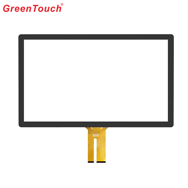
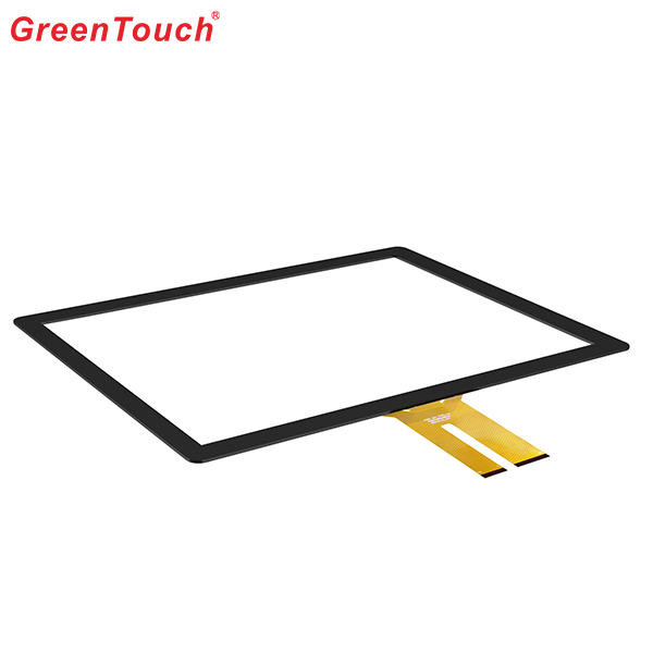
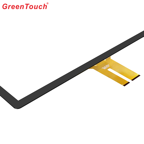
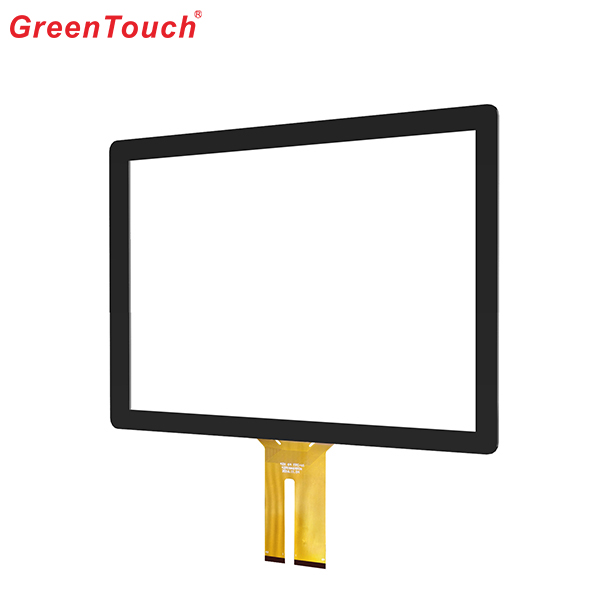
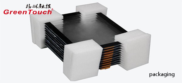
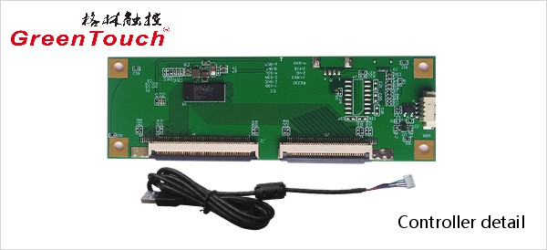
This product response time is shorter than resistive tonch screen's with a good touch.It is widely used to Phone,Tablet,E-book,gaming device by hands holding,Touch Monitor,GPS,All-In-One and so on.GreenTouch projected capacitive touch technology is with fast and sensitive response, the design with frame (without frame is optional) makes it looks professional and generous. The model is designed for high-intensity and high-frequency business environments.
Product show:
Capacitive Touch Screen Panel,Android Touch Screen,Portable Touch Screen,Pcap Touch Screen,POS Terminal Touch Screen,Mini Capacitive Touch Screen
ShenZhen GreenTouch Technology Co.,Ltd , https://www.bbstouch.com