Prof. Zhou Ligong's new book "Programming for AMetal Frameworks and Interfaces (Part 1)" introduces the AMetal framework in detail. By reading this book, you can learn highly multiplexed software design principles and development ideas for interface programming. Focus on your own "core domain", change your own programming thinking, and achieve common progress between the company and the individual. Authorized by Professor Zhou Ligong, from now on, the Zhiyuan Electronic Public Number will serialize the contents of the book, and is willing to share it.
Chapter VI peripheral driver code reuse, this article contains two sections after a small 6.3 RTC real time clocks:
6.3.6 RX8025T
6.3.7 DS1302
6.3 RTC Real Time Clock
> > > 6.3.6 RX8025T
In the MicroPort series expansion module, in addition to the RTC module of the PCF85063, the RX8025T module and the DS1302 module are both RTC expansion modules. The main differences are shown in Table 6.14.
Table 6.14 RTC chip comparison
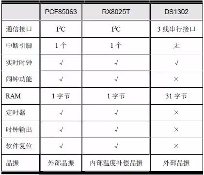
In the table, “√†indicates that the corresponding device supports this function, and “׆indicates that the corresponding device does not support this function.
1. Device introduction
The RX8025T is a real-time clock chip with a high stability 32.768KHz DTCXO (Digital Temperature Compensated Crystal Oscillator) I2C bus interface. It provides time and date setting and acquisition, alarm interrupt, time update interrupt, fixed cycle. Interrupt, temperature compensation and other functions. All addresses and data are transmitted over the I2C bus with a maximum bus speed of 400 kbps.
The RX8025T pin package is shown in Figure 6.6, where SCL and SDA are I2C interface pins, VDD and VSS are power and ground, respectively; CLKOUT is the clock output pin, which can be used to output clock signals; T1(CE), TEST, T2 The (Vpp) pin is for factory testing only. The NC is a pin that does not need to be connected. In actual use, these pins can be directly left floating. INT is an interrupt pin and is mainly used for alarm clock functions. CLK_EN is clock output enable. Pin, used to control the output of the CLKOUT clock.
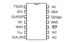
Figure 6.6 RX8025T pin definition
The 7-bit I2C slave address of the RX8025T is 0x32, and the module schematic is shown in Figure 6.7. If the MicroPort-RX8025T module is connected to the AM824-Core through the MicroPort interface, SCL and SDA are connected to PIO0_16 and PIO0_18 respectively, the INT pin is connected to PIO0_1, and the FOE is connected to PIO0_10.

Figure 6.7 RX8025T module circuit
2. Device initialization
Before using the RX8025T, the RX8025T initialization must be completed to obtain the corresponding operation handle, in order to use the various functions of the RX8025T. The prototype of the initialization function (am_rx8025t.h) is:

This function is intended to get the instance handle of the RX8025T device, where p_dev is a pointer to an instance of type am_rx8025t_dev_t and p_devinfo is a pointer to instance information of type am_rx8025t_devinfo_t.
(1) Example
An example of defining the am_rx8025t_dev_t type (am_rx8025t.h) is as follows:

Where g_rx8025t_dev is a user-defined instance whose address is passed as an argument to p_dev.
(2) Instance information
The example information mainly describes the inherent information of the specific device, that is, the connection information of the CLK_EN of the RX8025T and the INT pin to the microprocessor pin. The definition of its type am_rx8025t_devinfo_t (am_rx8025t.h) is as follows:

When the MicroPort-RX8025T module is connected to the AM824-Core via the MicroPort interface, INT and CLK_EN are connected to PIO0_1 and PIO0_10, respectively. Its instance information is defined as follows:

Where g_rx8025t_devinfo is user-defined instance information whose address is passed as an argument to p_devinfo.
(3) I2C handle i2c_handle
Taking I2C 1 as an example, the return value of its instance initialization function am_lpc82x_i2c1_inst_init () is passed as an argument to i2c_handle. which is:

(4) Example handle
RX8025T Initializes the return value of the function am_rx8025t_init () as the argument to the first parameter of the other function interface function (handle). The definition of am_rx8025t_handle_t type (am_rx8025t.h) is as follows:

If the return value is NULL, the initialization fails. If the return value is not NULL, the return value handle is valid.
Based on the modular programming idea, the definitions of the initialization related instances, instance information, etc. are stored in the corresponding configuration file, and the instance initialization function interface is extracted through the header file. The program examples of the source file and the header file are respectively shown in the program list 6.39 and the program. Listing 6.40.
Listing 6.71 Instance initialization function implementation (am_hwconf_rx8025t.c)
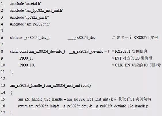
Listing 6.72 Instance Initialization Function Declaration (am_hwconf_rx8025t.h)

Subsequent only need to use the parameterless instance initialization function to get the instance handle of RX8025T. which is:

3. Use RTC function
Using the RTC function, you can use the RTC common interface to operate the RX8025T for time setting and acquisition. Before using the RTC common interface, you need to obtain an RTC handle of type am_rtc_handle_t. The driver of the RX8025T provides the corresponding interface for obtaining the RTC handle of the RX8025T, so that the user can operate the RX8025T through the RTC universal interface. The function prototype is:

This function is intended to get the RTC handle, where the handle of the RX8025T instance (rx8025t_handle) is passed as an argument to the handle, and p_rtc is a pointer to an instance of the am_rtc_serv_t type, with no instance information. Define the am_rtc_serv_t type (am_rtc.h) instance as follows

Where g_rx8025t_rtc is a user-defined instance whose address is passed as an argument to p_rtc.
Based on the modular programming idea, the initialization related instance definitions are stored in the corresponding configuration file, and the instance initialization function interface is extracted through the header file. The source file and the header file are respectively shown in the program list 6.73 and the program list 6.74.
Listing 6.73 adds the RTC instance initialization function for RX8025T (am_hwconf_rx8025t.c)

Listing 6.74 am_hwconf_rx8025t.h File Content Update (1)

Subsequent only need to use the parameterless RTC instance initialization function to get the RTC instance handle. which is:

After getting the handle, since the application written based on the RTC common interface can be multiplexed across platforms, you can start the RTC time display application as shown in Listing 6.45 directly based on the RX8025T. See Listing 6.75 for details.
Listing 6.75 Launching an RTC application (based on RX8025T)
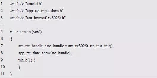
Obviously, if you change the RTC module from PCF85063 to RX8025T, the application core code does not need to be modified.
4. Use the alarm clock function
Use the alarm function to operate the RX8025T using the alarm universal interface. Before using the alarm universal interface, you need to get an alarm handle of type am_alarm_clk_handle_t. The RX8025T driver provides a corresponding interface for obtaining the alarm handle of the RX8025T, which is convenient for the user to operate the RX8025T through the alarm universal interface. The function prototype is:

This function is intended to get the alarm handle, where the handle of the RX8025T instance (rx8025t_handle) is passed as an argument to the handle, and p_alarm_clk is a pointer to an instance of type am_alarm_clk_serv_t with no instance information. An example of defining the am_alarm_clk_serv_t type (am_alarm_clk.h) is as follows:

Where g_rx8025t_alarm_clk is a user-defined instance whose address is passed as an argument to p_alarm_clk.
Based on the modular programming idea, the initialization related instance definitions are stored in the corresponding configuration file, and the instance initialization function interface is extracted through the header file. The source file and the header file are respectively shown in Listing 6.76 and Listing 6.77.
Listing 6.76 adds the alarm instance initialization function for RX8025T (am_hwconf_rx8025t.c)

Listing 6.77 am_hwconf_rx8025t.h file content update (2)

Subsequently, you only need to use the no-argument alarm instance initialization function to get the alarm instance handle. which is:

After the handle is acquired, since the application written based on the alarm clock common interface can be multiplexed across platforms, the alarm test application shown in Listing 6.54 can be started directly based on the RX8025T. See Listing 6.78 for details.
Listing 6.78 Launching the Alarm Test Application (based on RX8025T)
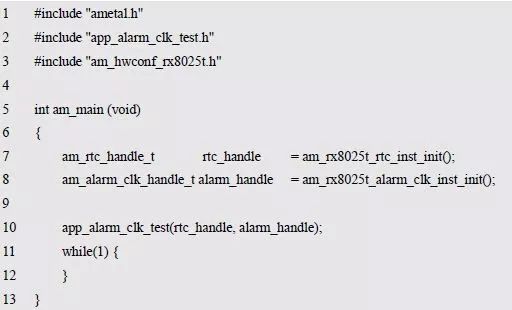
Obviously, if you change the RTC module from PCF85063 to RX8025T, the alarm application core code does not need to be modified.
5. Provide RTC services for system time
If you need to use the RX8025T to provide RTC services for system time, you only need to use the RTC handle obtained from RX8025T as the rtc_handle parameter of the system time initialization function when initializing the system time. which is:

For convenience of use, the call to the initialization function is added to the configuration file, and the instance initialization function interface of the system time is brought out by the header file. See Listing 6.79 and Listing 6.80 for details.
Listing 6.79 RX8025T is used as an instance initialization for system time (am_hwconf_rx8025t.c)

Listing 6.80 am_hwconf_rx8025t.h File Content Update (3)
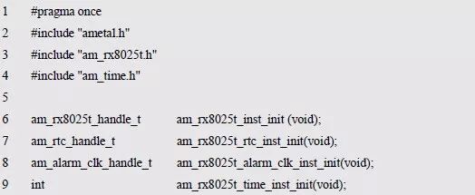
Subsequently, you only need to simply call the no-argument function to complete the initialization of the system time. which is:

After the system time is initialized, since the application written based on the system time common interface can be multiplexed across platforms, the system time test application shown in Listing 6.65 can be started directly based on the RX8025T. See Listing 6.81 for details.
Listing 6.81 Launching the System Time Test Application (based on RX8025T)
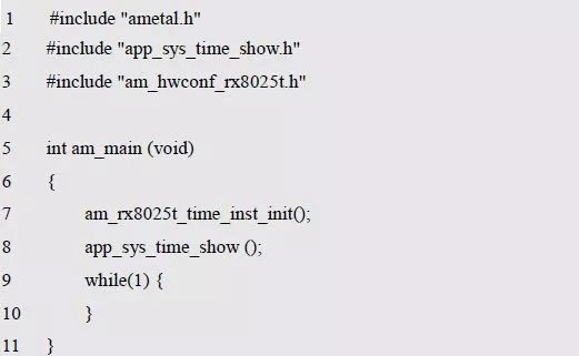
Obviously, if you change the RTC module from PCF85063 to RX8025T, the application using system time does not need to be modified.
6. Special function control interface
For the RX8025T, in addition to the typical clock and alarm functions, there are special features such as timers, clock outputs, 1-byte RAM, and more. These functions are not universal functions and can only be operated using the corresponding interface of the RX8025T. Take the read and write 1 byte RAM as an example, the corresponding interface function is shown in Table 6.15.
Table 6.15 Reading and Writing RAM Interface Functions (am_rx8025t.h)

(1) Write to RAM
This function is used to write 1 byte of data into the RAM of the RX8025T. The function prototype is:

Where handle is the RX8025T instance handle and data is the single byte data written. If AM_OK is returned, the data is written successfully, otherwise it fails. The sample program written to 0x55 to RAM is shown in Listing 6.82.
Listing 6.82 Writing to the RAM Sample Program

(2) Read RAM
This function is used to read the data stored in the single-byte RAM of the RX8025T. The function prototype is:

Where handle is RX8025T instance handle and p_data is output parameter for returning read single-byte data.
Return AM_OK, indicating that the reading was successful, and vice versa. The sample program is shown in Listing 6.83.
Listing 6.83 Read RAM Sample Program

You can use the read and write RAM interface to verify that the RX8025T is normal. See Listing 6.84 for details.
Listing 6.84 Read and Write RAM Data Sample Program
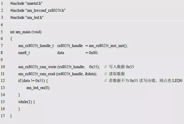
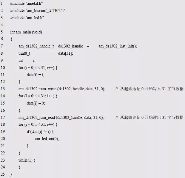
If the read/write data is in error, LED0 is lit. It can be seen that although the logic of the program is basically the same as the application shown in Listing 6.70, since the interface used is a special function control interface, which is related to a specific chip, it cannot be directly like the RTC application and the alarm application. Direct cross-platform reuse.
> > > 6.3.7 DS1302
1. Device introduction
The DS1302 is a trickle charge timer chip that includes a real-time clock and 31 bytes of static RAM that provides information such as year, month, day, hour, minute, and second, with leap year correction.
The DS1302 is designed to operate at very low power and maintain data and clock information below 1μW. In addition to the basic timing functions, the DS1302 has other features such as dual-pin mains and backup power, programmable trickle charger VCC1.
The DS1302 communicates with the microprocessor via a simple serial interface. Synchronous serial communication simplifies the interface between the DS1302 and the microprocessor. Communication requires only three wires: CE, I/O (data line), SCLK (serial clock). . The pin package diagram of the DS1302 is shown in Figure 6.8.
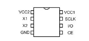
Figure 6.8 DS1302 pin definition
Among them, X1 and X2 are the pins of the external crystal, which need to be connected to the standard 32.768kHz quartz crystal. SCLK, CE, and I/O are serial communication pins to the microprocessor. GND is the power ground, VCC1 and VCC2 are the power supply pins. This is also the characteristic of the DS1302, namely: dual-pin main power supply and backup power supply. In the dual-pin, VCC2 is the main power supply, and VCC1 is the backup power supply. Rechargeable Battery. The DS1302 is powered by the larger of VCC1 or VCC2. When VCC2 is greater than VCC1+0.2V, VCC2 supplies power to the chip. When VCC2 is less than VCC1, the chip is powered by VCC1. When the chip is powered by VCC2, VCC1 is not powered. At the same time, a programmable trickle charger can be used to make VCC2 flow a small amount of current into VCC1 to charge the battery connected to VCC1. Of course, VCC1 can not be connected to the rechargeable battery. In this case, it is only necessary to control the programmable trickle charger so that VCC2 does not flow current to VCC1.
The schematic of the DS1032 module is shown in Figure 6.9. If the MicroPort-DS1302 module is connected via the MicroPort interface AM824-Core, SCLK, I/O and CE are connected to PIO0_15, PIO0_13 and PIO0_14 respectively.

Figure 6.9 DS1302 Module Circuit
2. Device initialization
Before using the DS1302, the initialization of the DS1302 must be completed to obtain the corresponding operation handle, so that the various functions of the DS1302 can be used. The prototype of the initialization function (am_ds1302.h) is:

This function is intended to get the instance handle of the DS1302 device, where p_dev is a pointer to an instance of type am_ds1302_gpio_dev_t and p_devinfo is a pointer to instance information of type am_ds1302_gpio_devinfo_t.
(1) Example
The definition of the am_ds1302_gpio_dev_t type (am_ds1302.h) is as follows:

Where g_ds1302_gpio_dev is a user-defined instance whose address is passed as an argument to p_dev.
(2) Instance information
The example information mainly describes the inherent information of the specific device, that is, the connection information of the SCLK, I/O, CE pin of the DS1302 and the microprocessor pin. The definition of its type am_ds1302_gpio_devinfo_t (am_ds1302.h) is as follows:

When the MicroPort-DS1302 module is connected to the AM824-Core through the MicroPort interface, SCLK, I/O, and CE are connected to PIO0_15, PIO0_13, and PIO0_14, respectively. Its instance information is defined as follows:

Where g_ds1302_gpio_devinfo is user-defined instance information whose address is passed as an argument to p_devinfo.
(3) instance handle
The return value of the initialization function am_ds1302_gpio_init() of DS1302 is passed as the actual parameter to the first parameter (handle) of other function interface functions. The definition of the am_ds1302_handle_t type (am_ds1302.h) is as follows:

If the return value is NULL, the initialization fails. If the return value is not NULL, the return value handle is valid.
Based on the modular programming idea, the definitions of the initialization related instances, instance information, etc. are stored in the corresponding configuration file, and the instance initialization function interface is extracted through the header file. The program examples of the source file and the header file are respectively shown in the program list 6.85 and the program. Listing 6.86.
Listing 6.85 Example Initialization Function Implementation (am_hwconf_ds1302.c)

Listing 6.86 Example Initialization Function Declaration (am_hwconf_ds1302.h)

Subsequent only need to use the parameterless instance initialization function to get the instance handle of DS1302. which is:

3. Use RTC function
Use the RTC function to operate the DS1302 setup and acquisition time using the RTC Universal Interface. Before using the RTC Universal Interface, you need to obtain an RTC handle of type am_rtc_handle_t. The driver of the DS1302 provides a corresponding interface for obtaining the RTC handle of the DS1302, which is convenient for the user to operate the DS1302 through the RTC universal interface. The function prototype is:

This function is intended to get the RTC handle, where the handle of the DS1302 instance (ds1302_handle) is passed as an argument to the handle, and p_rtc is a pointer to an instance of the am_rtc_serv_t type, with no instance information. An example of defining the am_rtc_serv_t type (am_rtc.h) is as follows:

Where g_ds1302_rtc is a user-defined instance whose address is passed as an argument to p_rtc.
Based on the modular programming idea, the initialization related instance definitions are stored in the corresponding configuration file, and the instance initialization function interface is extracted through the header file. The source file and the header file are respectively shown in the program list 6.87 and the program list 6.88.
Listing 6.87 adds the RTC instance initialization function for DS1302 (am_hwconf_ds1302.c)

Listing 6.88 am_hwconf_ds1302.h File Content Update (1)

Subsequent only need to use the parameterless RTC instance initialization function to get the RTC instance handle. which is:

After the handle is acquired, since the application written based on the RTC common interface can be multiplexed across platforms, the RTC time display application as shown in Listing 6.45 can be started directly based on the DS1302.
Listing 6.89 Starting the RTC application (based on DS1302)
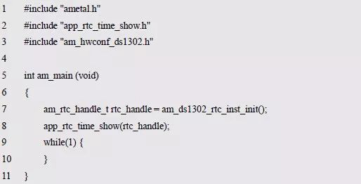
It can be seen that if the RTC module is replaced by the PCF85063 to the DS1302, the application core code does not need to be modified.
4. Provide RTC services for system time
Since the DS1302 does not support the alarm function, you cannot operate the DS1302 with the universal alarm interface. If you need to use the DS1302 to provide RTC services for system time, you only need to use the RTC handle obtained from DS1302 as the rtc_handle parameter of the system time initialization function when initializing the system time. which is:

In order to facilitate the use of the call to initialize the function is added to the configuration file, the instance of the system time is initialized through the header file. See Listing 6.90 and Listing 6.91 for details.
Listing 6.90 DS1302 is used as an instance initialization for system time (am_hwconf_ds1302.c)

Listing 6.91 am_hwconf_ds1302.h file content update (2)
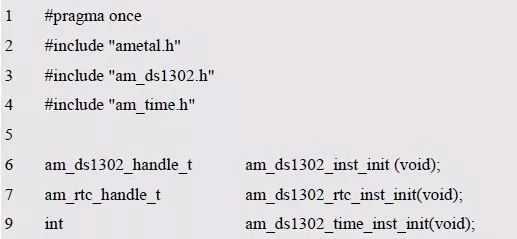
Subsequently, you only need to simply call the no-argument function to complete the initialization of the system time. which is:

After the system time is initialized, since the application written based on the system time common interface is reusable, the system time test application as shown in Listing 6.65 can be started directly based on the DS1302. See Listing 6.92 for details.
Listing 6.92 Launching the System Time Test Application (based on DS1302)
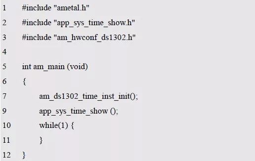
Obviously, if you change the RTC module from PCF85063 to DS1302, the application using system time does not need to be modified.
5. Special function control interface
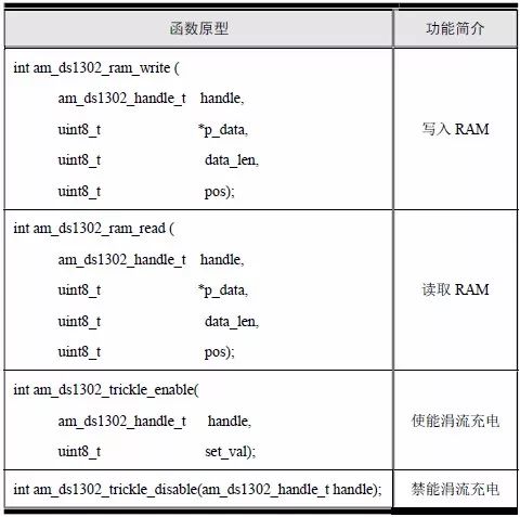
In addition to the typical real-time clock function, the DS1302 has special features such as trickle charge, 31-byte RAM, and more. These functions can only be operated using the corresponding interface of the DS1302 because they are not universal functions. Take the read and write RAM and trickle charging functions as an example. The corresponding interface functions are shown in Table 6.16.
Table 6.16 DS1302 Special Function Control Interface (am_ds1302.h)
(1) Write to RAM
This function is used to write data to the RAM of the DS1302 (up to 31 bytes of data can be written). The function prototype is:

Where handle is the DS1302 instance handle, p_data points to the first address of the data to be written, data_len specifies the number of bytes to write data, up to 31 bytes, pos specifies the starting address to be written to RAM, and the RAM size of DS1302 It is 31 bytes, the corresponding address is 0 ~ 30, and the valid range of pos is 0 ~ 30. If AM_OK is returned, the data is written successfully, otherwise it fails. The sample program for writing 31 bytes of data to RAM is shown in Listing 6.93.
Listing 6.93 Write RAM Sample Program

(2) Read RAM
This function is used to read the data stored in the RAM of the DS1302. The function prototype is:

The handle is the DS1302 instance handle, p_data is the output parameter, which is used to return the read data, data_len is the number of bytes of the read data, and pos is the starting address of the read data (0 ~ 30). If AM_OK is returned, the read is successful, and vice versa. The sample program is shown in Listing 6.94.
Listing 6.94 Read RAM Sample Program

You can use the read-write RAM interface to verify that the DS1302 is functioning properly. See Listing 6.95 for details.
Listing 6.95 Read and write RAM data sample program
(3) Enable trickle charging
The DS1302 has dual power supplies. When the chip is powered by VCC2, a programmable trickle charger can be used to make VCC2 flow a small amount of current into VCC1 to charge the battery connected to VCC1. The function prototype that enables trickle charging is:

Among them, the handle is the DS1302 instance handle, and set_val is the control parameter of the programmable trickle charger, which can control the charging current. A schematic diagram of the charging circuit is shown in Figure 6.10.

Figure 6.10 Schematic diagram of the DS1302 charging circuit
When the main switch is turned on, the magnitude of the charging current is determined by the number of selected diodes (1 or 2) and the resistance (2KΩ, 4KΩ or 8KΩ). The number of diodes determines the voltage drop of the voltage. The current is calculated as:

The available values ​​for set_val have been defined using macros. For details, see Table 6.17. In actual use, you should select one of the macros as the value of set_val according to the required current.
Table 6.17 Charging circuit setting flags
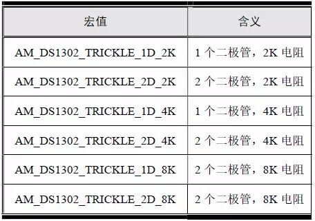
For example, if you select 1 diode, 2K resistor, you should set the value of set_val to:
AM_DS1302_TRICKLE_1D_2K
Since the value of VCC2 is 3.3V in the MicroPort-DS1302, the actual current calculation formula at this time is:

When VCC1 is 0 (the battery is completely depleted), the current reaches its maximum value, which is:

This requires a battery to support a maximum charge current of 1.3mA. In practice, as the battery is charged, the battery power increases, VCC1 gradually increases, and the charging current also decreases. The sample program is detailed in Listing 6.96.
Listing 6.96 Enables the trickle charge sample program

(3) Disabled trickle charging
When no charging is required, such as the non-rechargeable battery used, the interface can be used to disable trickle charging. The function prototype is:

Among them, the handle is the DS1302 instance handle, and the sample program is shown in Listing 6.97.
Listing 6.97: Disabled trickle charge sample program

Insulated Copper Tube Terminals
Insulated Copper Tube Terminals,High quality insulated terminal,copper tube terminal
Taixing Longyi Terminals Co.,Ltd. , https://www.longyicopperterminals.com