As a programmable logic design environment, Altera Quartus II is increasingly welcomed by designers of digital systems due to its powerful design capabilities and intuitive and easy-to-use interfaces. The latest official version available for download is v17.0.
Altera Quartus II (3.0 and later) design software is the industry's only design tool that provides a unified design flow for FPGA and fixed-function HardCopy devices. Engineers use the same low-cost tools for functional verification and prototyping of Stratix FPGAs, and they can design HardCopy Stratix devices for volume production. System designers can now use the Quartus II software to evaluate the performance and power consumption of HardCopy Stratix devices, with corresponding maximum throughput designs.
Altera's Quartus II programmable logic software is a fourth-generation PLD development platform. The platform supports design requirements in a workgroup environment, including support for Internet-based collaborative design. The Quartus platform is compatible with development tools from EDA vendors such as Cadence, ExemplarLogic, Mentor Graphics, Synopsys, and Synplicity. Improved LogicLock module design features of the software, added FastFit compiler options, promoted network editing performance, and improved debugging capabilities.
Quartus download and crack tutorial1, download quartus ii 13.1 official file package, in order to avoid the installation package contains and device, it is best to download the official website altera, do not use some people in the cloud disk.

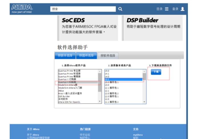
2. After entering the official website, find the download options. See the figure above. Select the software selection assistant in the pop-up interface. Select quartus ii 13.1 and click Download. As shown in the figure below, the download method is recommended for direct download. In order to avoid the trouble of device installation, it is recommended to directly download the assembly file. After clicking on the download, it will ask you to log in to the altera account and use the email to register one, which is not repeated here.
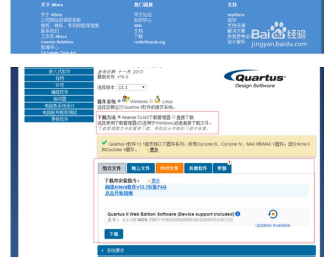
3, because the file is relatively large, the download may take some time, this is to read the book, after downloading, use the decompression software to extract rar, after decompression, double-click the setup (the setup here is the windows batch file), wait for the pop-up installation Interface, and then you can point to next, because it is very simple, not repeat them.
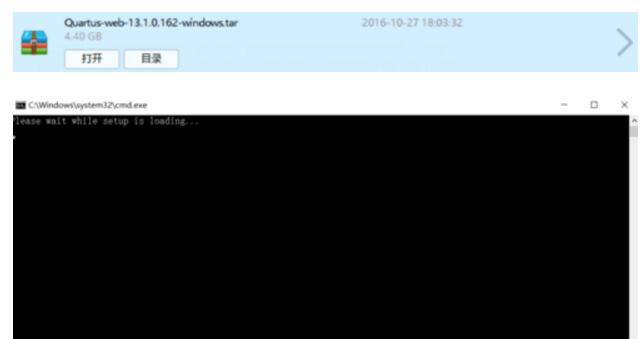
4, the installation time is longer, it takes about 20 minutes, this is we can go to the next quartus cracker, after all, can not be a waste of time. Since the link will be blocked, I will not post the link. You directly search for the Quartus_13.1_x64 cracker (64-bit version), you can download one (recommended to download the top).
5, after downloading, the software is almost installed, double-click to open the downloaded Quartus_13.1_x64 cracker, click on the application, it may remind you that the file was not found, click OK to find the file, if you install quartus, the software location By default, the file is usually in the C:\altera\13.1\quartus\bin64 directory. Select the file with the suffix dll, click Open, and then click Save. This is where you can see that the cracker prompts the patch to finish running.
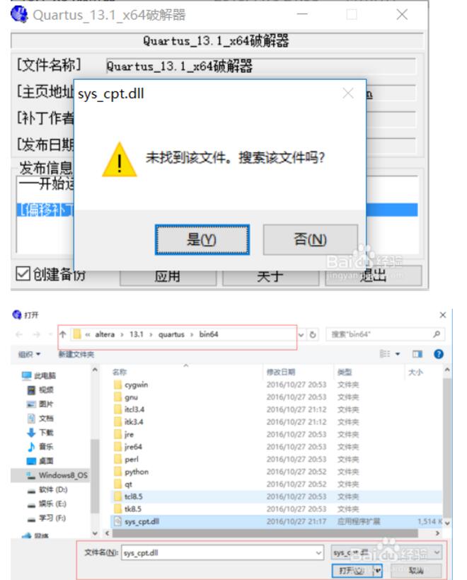
6. After you click Quit, the cracker will ask you to open a bat file, select Open with Notepad, and then replace all the XXXXXXXXXXXXX with your network card number. After saving, quartus That is cracked successfully.
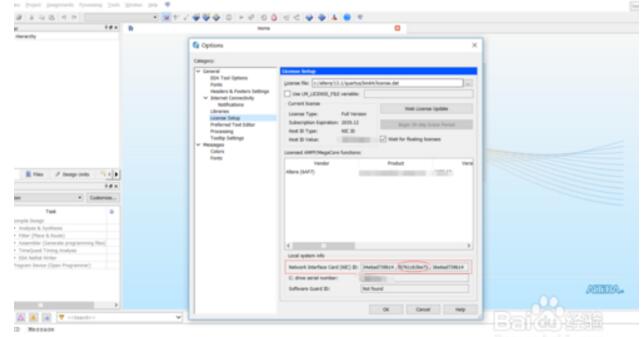
7, then how do you know your network card is good. Open quartus, select tools-license to obtain the network card number (Note: there are multiple network card numbers, only one copy is required).
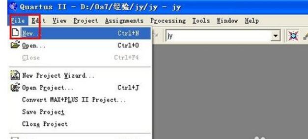
1. Here we have created a new project by default. Click [New] in the [File] menu. The user design creation wizard will pop up. Select the [Design Files]-[Block Diagram/Schematic File] schematic in [New]. File input
2,
3,
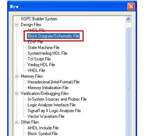
4, the establishment of schematic design documents
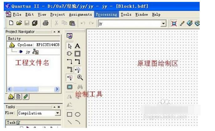
5, call the parameterized components, double-click the left mouse button in the drawing area, which will pop up the window to add symbolic components
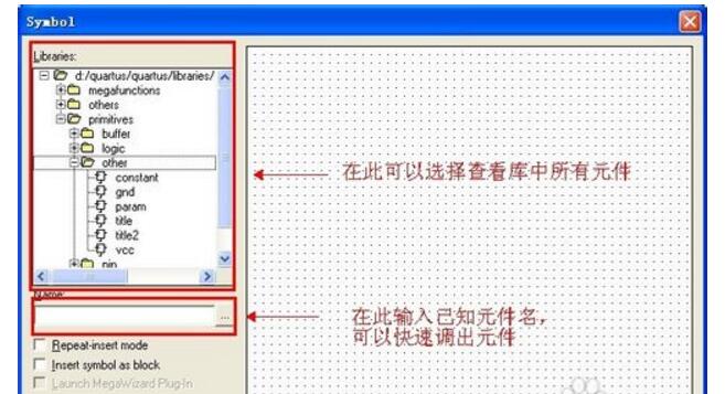
6, respectively, call the input port "input" and logic device "74138"
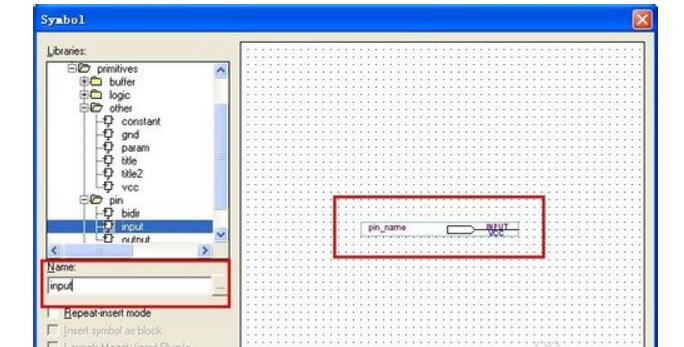
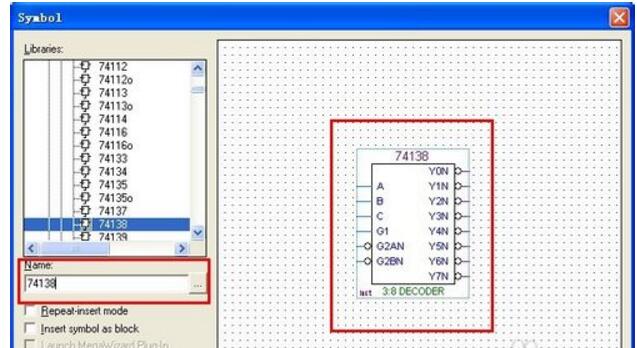
7, drawing control operation, use the zoom tool button, switch back to the button (select and draw tools) in order to edit the drawing.
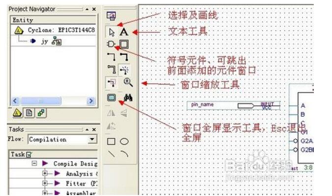
8, from the symbol library call out the required input and output ports, neat emissions
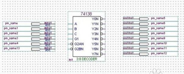
9, to complete the line connection operation (the mouse is placed at the endpoint, will automatically capture, press the left button and drag to the target, after the release of a line to complete the operation)
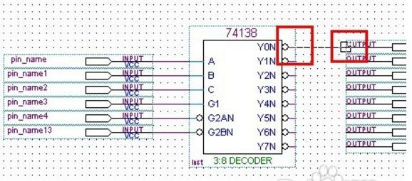
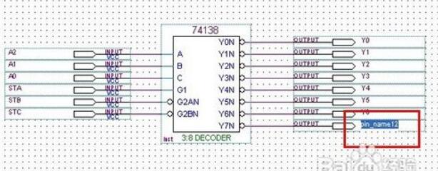
10. Double-click the port name with the left mouse button, as shown in the figure 74138 Circuit Y7N, enter the user-defined name directly. 74138 logic test circuit schematic design is completed!
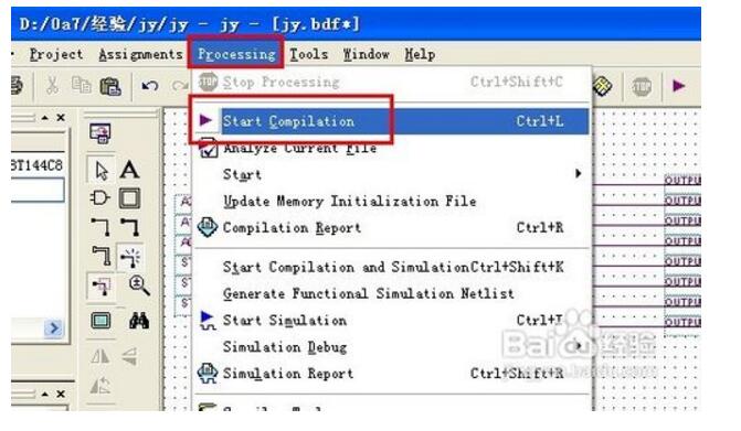
11, in the drop-down menu [Processing] select [Start Compilation], start full compilation
12. Compilation and analysis report:
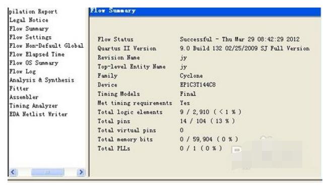
13. Select Processing/Start Compilation to automate the entire process of analysis, troubleshooting, synthesis, adaptation, assembly, and timing analysis.
14. During compilation, the error message is indicated by the lower information bar (red font). Double-click on this information to locate the error. Compile it here to eliminate all errors.
15. After the compilation is successful, a compilation report will pop up showing relevant compilation information.
16, QuartusII compiler consists of a series of processing modules; these modules are responsible for the design project's error detection, logic synthesis, structure synthesis, output configuration editing, and timing analysis;
17, in this process, the design project is adapted to the FPGA / CPLD target device, while generating a multi-purpose output file, such as function and timing information files, device programming object file;
18. The compiler first checks out the possible error information in the engineering design file for the designer to eliminate, and then produces a structured circuit diagram file representation of the circuit diagram file;
19. After the project is compiled, whether the design results meet the design requirements can be analyzed through the timing simulation; create a waveform vector file
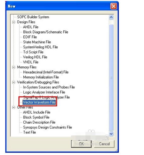
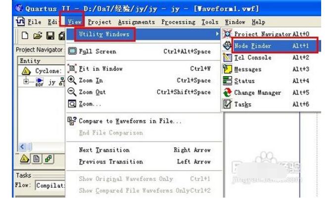
20, add the pin node, select the menu [View] - [Utility Windows] - [Node Finder] command
21. Under Filter select "Pins:unassigned" and click "List" to list the pin ports
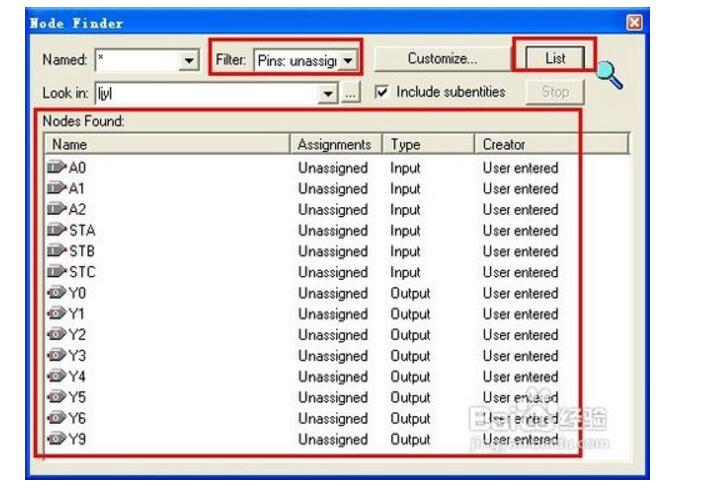
22. Select the listed port under the list below Nodes Found and drag it to the pin editing area of ​​the waveform file.
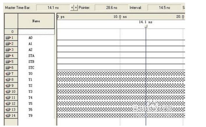
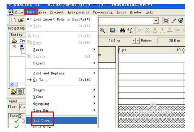
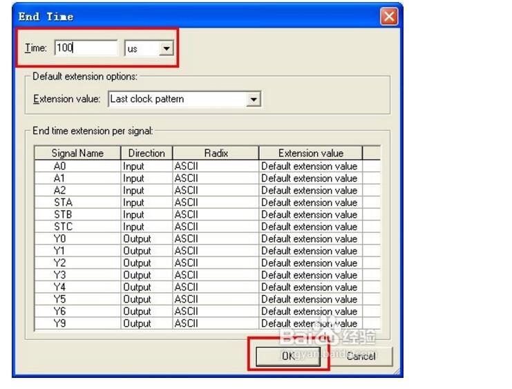
23, set the simulation time length, select the menu [Edit] - [End Time] command, the default is 1us, here it is set to 100us
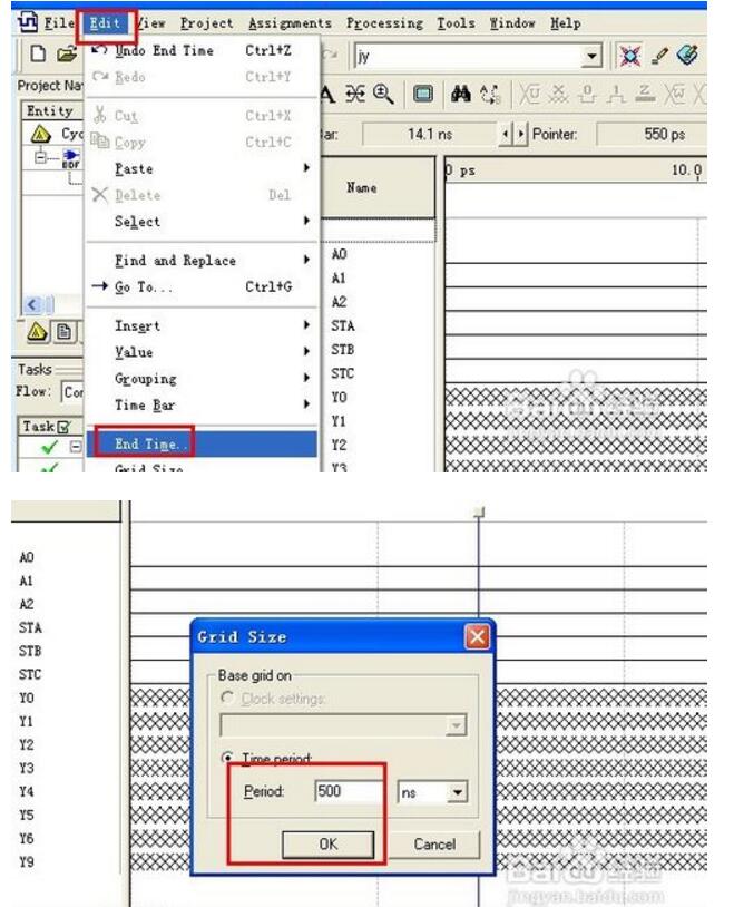
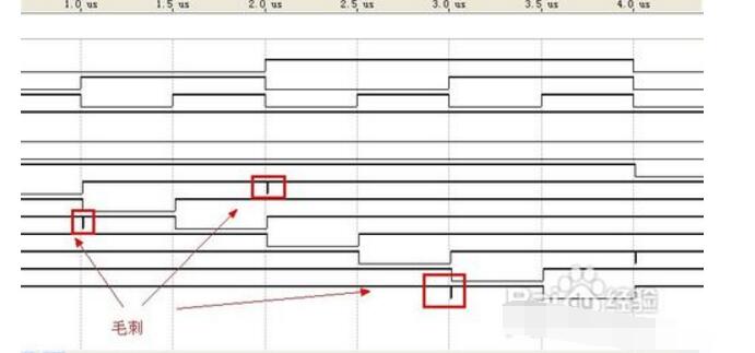
24, set the simulation time period, select the menu [Edit] - [Grid Size ...] command, the default is 10ns, due to the existence of a competitive adventure, in the simulation signal waveform and a large number of glitches mixed together, affecting the simulation results, so here Set to 500ns
25, edit the input port signal, use the window zoom (left zoom, right zoom) to scale the waveform to the right level
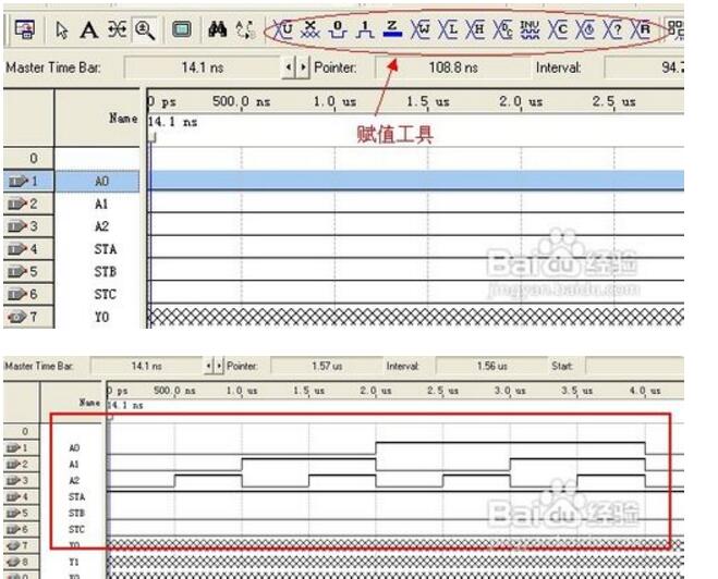
26. Start the timing simulation. Select [Start Simulation] in the drop-down menu [Processing]. The analysis waveform is visible. It is consistent with the 74LS138 function truth table and the result is correct.
Precautions
1, QuartusII through the "Project" to manage the design file, you must create a folder for this project to place all the design files associated with this project;
2, this folder name should not use Chinese, it is best not to use numbers, should be placed on the disk easy to find, do not put in the software installation directory;
3, set up the project folder and then follow-up operations ...
3 Mm /8 Mm Nano Tip,Electronic Board Marker Pen,Touch Board Marker Pens,Infared Smart Board Marker
Shenzhen Ruidian Technology CO., Ltd , https://www.wisonens.com