Portable devices that use LED-type solid-state lighting (SSL) require the use of highly efficient drive circuits to extend battery life, while also requiring the use of some brightness adjustment methods to adjust the light output to suit the surrounding lighting environment. In applications such as smart phones or portable GPS navigation systems for backlighting, LED brightness adjustment must be used in order to allow the user to see the screen in both strong sunlight and low light conditions at night. When using flashlights, users believe that longer battery life is more important than providing the strongest light illumination. We can use analog brightness adjustment or pulse width modulation (PWM) brightness adjustment methods in these applications. Analog designs use an innovative approach to establish a reference voltage, resulting in higher efficiency than PWM-type designs.
Both analog and PWM brightness adjustment methods control the LED drive current, which is proportional to the light output. The analog brightness adjustment structure is simple, the control power consumption is the lowest, and is generally more efficient than the PWM brightness adjustment method because the LED forward voltage is lower when the driving current is low.
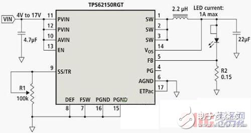
However, analog dimming requires an analog voltage to be generated from a separate voltage reference (either using an RC filter output for a square wave input signal or using an expensive digital-to-analog converter (DAC)). The circuit shown in Figure 1 does not have the complexity of these methods by modifying a potentiometer, thus achieving a simple, cost-effective analog brightness adjustment method. This total solution is an efficient, low-cost, low-component-count LED driver for a single high-current LED, such as OSRAM's Golden Dragon, which can be used in some small battery-powered devices.
Circuit operation

Figure 1. Analog brightness adjustment LED driver implemented by potentiometer R1
The circuit requires a voltage-regulated, synchronous, buck converter that delivers up to 1A of output current from a 17V supply, such as the TPS62150. In Figure 1, this buck converter uses a feedback (FB) pin to control the voltage across the sense resistor R2 and regulate the LED current. The FB voltage is controlled by a precision internal reference voltage (typically 0.8V) and an SS/TR (slow start and track) external input pin.
When the SS/TR pin voltage is lower than 1.25V, the FB pin voltage is equal to the SS/TR pin voltage multiplied by 0.64, that is, VFB = 0.64 * VSS/TR. By controlling the FB voltage to control the voltage of R2, the IC can change the current that drives the LED.
The SS/TR pin has an embedded current source, which is typically 2.5 μA. This power supply is commonly used to charge capacitors and form a smooth, linear SS/TR pin voltage rise. In a typical buck converter, this results in a linear, controlled rise in the output voltage while also reducing the inrush current of the input supply. With this design, a ground resistor generates a constant voltage on the SS/TR pin.
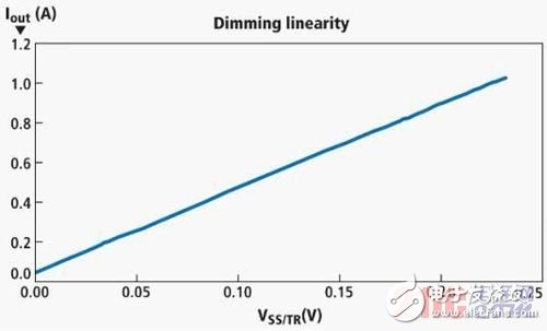
A potentiometer is placed on the SS/TR pin to keep the voltage between 250mV (potentiometer = 100kΩ) and 0V (potentiometer = 0Ω). Recalling the above equation, it means that the FB pin voltage range is between 160 mV and 0V. When R2 is a 0.15 Ω resistor, the LED current range is 1.07A-0A. Since the FB pin voltage is linearly related to the SS/TR pin voltage, the potentiometer provides linear analog brightness adjustment as shown in Figure 2.

The brightness adjustment linearity of the circuit shown in FIG. 2 and FIG. 1 uses a potentiometer to achieve brightness adjustment.
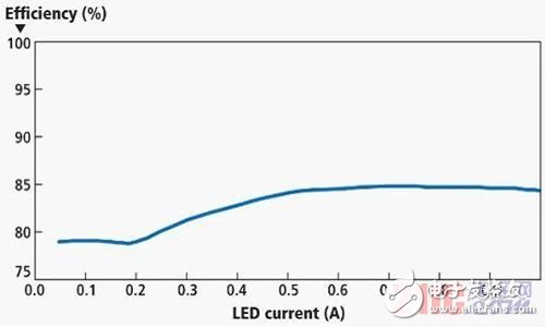
This circuit has a very high efficiency because the value of the FB pin voltage is relatively low. This low voltage can reduce the power consumption of the detection resistor R2. In addition, the TPS62150 uses energy-saving mode at light load current conditions to maintain high efficiency over most load ranges. Figure 3 shows the efficiency of the circuit shown in Figure 1, which uses a 12V input and uses TDK's VLF3012ST-2R2 inductor during the switching output.
We can increase the efficiency of this circuit, but the cost is to increase the circuit size. For example, you can connect the output voltage to the FSW (switching frequency) control pin to reduce the operating frequency, and/or choose a low DCR (DC resistance) and/or inductor with better AC loss characteristics. Although implementing these two methods may require more board area, it can achieve more than 90% efficiency. Although its efficiency is not the highest, the design shown in Figure 1 has a smaller solution size and better work efficiency.
Circuit limitations
Since this circuit uses a non-precise analog input (a manually adjustable potentiometer) to regulate the LED current, the sense resistor, potentiometer resistance, and tolerance of the SS/TR pin current and its effect on the LED brightness are all Not so important. If the LED is too bright, the user can simply turn down the potentiometer resistance. If it is too dark, just increase the potentiometer resistance. Using a multi-directional potentiometer, we can effectively control the LED brightness for many general applications such as flashlights and backlights.
One disadvantage of this design is the compensation between the SS/TR pin and the FB pin voltage. When the SS/TR pin is pulled down to 0V, a 50mA current can still flow through the LED by reducing the potentiometer resistance. Therefore, the LED cannot be completely turned off unless you add a grounding switch with a pull-up resistor connected to the EN pin.
Other analog brightness adjustment methods
The advantages of using a potentiometer circuit as described herein are its simplicity and cost effectiveness. The analog voltage required to simulate the brightness adjustment is generated by a precision current source of the IC and then converted to the corresponding light output by a user-adjustable resistor. With the exception of this potentiometer, there is no need to use any other components. The dimming input, the potentiometer, is the only component required.

The efficiency of the circuit shown in Figure 3 and Figure 1 in the brightness adjustment range.
Without this precise current source, we need to consider using other methods to generate the analog voltage needed for analog brightness adjustment. Some conventional methods include: using a separate reference voltage IC to generate an accurate analog voltage; changing the duty cycle of the microcontroller's PWM output through an RC filter to produce an accurate analog voltage; or using a microcontroller with a DAC to generate the exact Analog voltage. All of these methods require user input to change the light output. When using a reference voltage IC, it is still required to use a potentiometer as the input of the IC to adjust the voltage and control the light output. The cost of the benchmark IC method is higher than the simple method highlighted in this article.
The last two methods require the use of a microcontroller, which also increases the cost of the solution. Although both smart phones and GPS systems include a microcontroller, the general flashlight does not. Which method you use depends on the application at hand, because some products require a more user-friendly interface (possibly using touch screen controls).
The third method uses a larger and more expensive DAC instead of a potentiometer. The DAC has a better output analog voltage interval size, so its light output control is also more accurate than the potentiometer. The specific application determines whether this high price is worth it.
The use of a potentiometer on the SS/TR pin of a buck converter is a simple, small, low-cost method that provides linear analog brightness adjustment for high-current LEDs in applications such as backlight and flashlight lighting. When using the analog brightness adjustment, using a 12V input power supply can maintain about 85% efficiency over most of the brightness adjustment range. The complete circuit requires only 6 components plus high-power LEDs.
Antenk DVI Series Digital Video Interface connectors are the standard digital interface for flat panels, video graphics cards, monitors and HDTV units. This series includes DVI-D (Digital), DVI-A (Analog) and DVI-I (Integrated Digital/Audio). Their unique crossing ground blades provide high speed performance at low cost. They are available in Straight or Right Angle PCB mount receptacles and mating male cable connectors. They support a data transfer rate of 4.95Gbps with a dielectric withstanding voltage of 500VAC. Each version features our specially designed contacts which improve signal performance and a zinc alloy shield that reduces electromagnetic interference (EMI).
Digital Visual Interface Cable Connectors
DVI ConnectorWith the advent of technologies such as DVD players, high-definition televisions, and even digital cable, the need for more advanced cables and connectors has increased. Digital Visual Interface (DVI) is one response to the growing need for interconnected systems, enabling digital systems to be connected to an array of displays. Yet DVI cables and connectors can also be complicated, and may lead to confusion between High Definition Multimedia Interface (HDMI) and DVI. Although the two systems have much in common, they service different niches of digital technology.
Digital Visual Interface
Older systems aren`t necessarily outdated systems. Although DVI preceded HDMI, it`s still widely used in both business and domestic settings. DVI connectors are designed to handle digital data transmission, incorporating three transmission channels in every connector link. The maximum bandwidth for data transfer is 165 megahertz, which is enough to relay up to 165 million pixels per second. Data is encoded for effective transfer, but a single link can handle around 4.95 gigabits per second of information. Double links can handle twice that amount.
Because a DVI cable carries information over a 165 megahertz bandwidth, complete digital resolution can be obtained. Using double link connectors increases the speed of transmission, but requires another cable. However, not many devices depend solely on a double link DVI, so this technolgy can be used on an as-desired basis.
Types of DVI Connectors
There are three general categories of DVI cable connectors: DVI-Digital (DVI-D), DVI-Integrated (DVI-I), and DVI-Analog (DVI-A). However, most connectors fall into one of the first two groups.
A standard DVI Connector is 37 mm wide and has 24 pins, 12 of which are used for a single link connection. When analog is involved, four additional pins are needed to support the additional lines of an analog signal. It is not possible to cross from a digital source to an analog display or vice versa. In those instances, an integrated connector is probably the best option. There are five common types of DVI connectors.
DVI-I Single Link
This kind of connector has three rows, each with six pins. There are two contacts. Because the connector is integrated, it can be used with both analog and digital applications.
DVI-I Dual Link
A DVI-I dual link connector can also be used with both digital and analog applications, but is configured with more pins to accommodate a dual connection. There are three rows with eight pins each, as well as two contacts.
DVI-D Single Link
Specifically designed for digital applications, a DVI-D single link connector has three rows of six pins, and looks much like a DVI-I single link connector. However, a DVI-D connector has no contacts.
DVI-D Dual Link
Also made specifically for digital applications, a DVI-D dual link features more pins (three rows of eight) for dual connections. Like a DVI-D single link, a DVI-D dual link connector has no contacts.
DVI-A
This particular type of connector can only be used for analog applications, and has three rows of pins. One row has five pins, one has four pins, and the last row has three pins. Like single link connectors, a DVI-A link connector has two contacts.
Male DVI Connector
ShenZhen Antenk Electronics Co,Ltd , https://www.antenksocket.com