This application note uses the OLED display that drives the SPI interface as an example to illustrate how to add the SPI device driver framework and underlying hardware drivers and use the SPI device driver interface to develop applications. Also given is a code example verified on the punctual atomic STM32F4 explorer development board.
1 The purpose and structure of this article
1.1 Purpose and Background of the Paper
The Serial Peripheral Interface Bus (SPI) is a synchronous serial communication interface specification for short-range communication and is mainly used in a single-chip microcomputer system. SPI is mainly used in EEPROM, FLASH, real-time clock, AD converter, digital signal processor and digital signal decoder. The use of four or three wires on the pins of a chip is easy to use, and more and more chips integrate such a communication interface.
In order to facilitate application layer program development, SPI device driver framework was introduced in RT-Thread. This article explains how to use the RT-Thread SPI device driver.
1.2 The structure of this article
This article first briefly introduced the RT-Thread SPI device driver framework and then run the SPI device driver sample code on the punctual atomic STM32F4 Explorer development board. Finally, the method of using SPI device driver framework interface and parameter values ​​are described in detail.
2 Introduction to SPI Device Driver Framework
The RT-Thread SPI device driver framework virtualizes the MCU's SPI hardware controller to the SPI bus (SPI BUS#n). Many SPI devices (SPI BUS#0 CSm) can be attached to the bus. Each SPI device can only be mounted to one. On the SPI bus. Currently, RT-Thread has implemented many common SPI device drivers, such as SD cards, various series of flash memory, and ENC28J60 Ethernet modules. The hierarchy of the SPI device driver framework is shown below.

Figure 2-1 SPI Device Driver Framework Hierarchy
Based on the previous introduction, the user has a general understanding of the RT-Thread SPI device driver framework, then how does the user use the SPI device driver framework?
3 Run the sample code
This chapter is based on the punctuality atom explorer STM32F4 development board and SPI sample code, and gives the use of the RT-Thread SPI device driver framework.
3.1 Sample Code Hardware and Software Resources
RT-Thread source code
ENV tool
SPI device driver sample code
Punctual Atomic STM32F4 Explorer Board
1.5 inch color OLED display (SSD1351 controller)
MDK5
The MCU of the punctuality atomic explorer STM32F4 development board is the STM32F407ZGT6. This example uses the USB to serial port (USART1) to send data and power, and uses the SEGGER J-LINK to connect JTAG debugs. STM32F4 has multiple hardware SPI controllers. SPI1 is used in this example. Color OLED display on board SSD1351 controller, resolution 128*128.
The connections between the STM32F4 and OLED display pins are shown in the following table:
| PA5 | D0 | SPI1 SCK, Clock |
| PA6 | SPI1 MISO, unused | |
| PA7 | D1 | SPI1 MOSI, Master Output, Slave Input |
| PC6 | D/C | GPIO, Output, Command 0/Data 1 Selection |
| PC7 | RES | GPIO, output, reset, active low |
| PC8 | CS | GPIO, output, chip select, active low |
| 3.3V | VCC | powered by |
| GND | GND | Grounding |
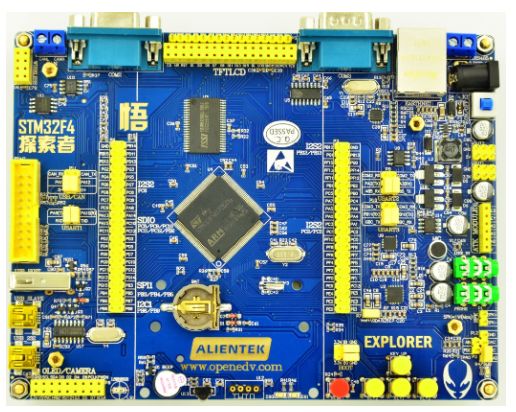
Figure 3.1-1 Positive Atomic Development Board
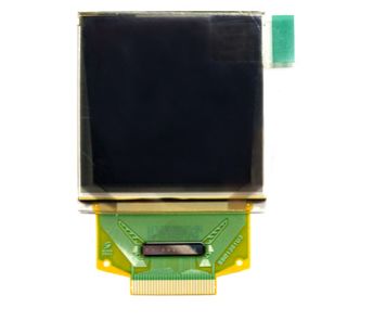
Figure 3.1-2 Color OLED Display
SPI device driver sample code includes app.c, drv_ssd1351.c, drv_ssd1351.h3 files, drv_ssd1351.c is the OLED display driver file, this driver file contains the SPI device ssd1351 initialization, mounted to the system and through the command to control the OLED The displayed operation method. Due to the versatility of the RT-Thread upper application API, these codes are not limited to specific hardware platforms, and users can easily port it to other platforms.
3.2 Configuration Engineering
Use menuconfig to configure the project: Use the cd command at the env utility command line to enter the rt-thread\bsp\stm32f4xx-HAL directory, and then enter the menuconfig command to enter the configuration interface.
Modify the engineering chip model: Modify the Device type to STM32F407ZG.
Configure the shell to use the serial port 1: Select Using UART1, enter the RT-Thread Kernel ---> Kernel Device Object menu, modify the device name for console to uart1.
Open the SPI bus and device driver and register the SPI bus to the system: Go to the RT-Thread Components ---> Device Drivers menu and select the Using SPI Bus/Device device drivers. The default SPI interface will default to Using SPI1. The spi1 bus device will Register to operating system.
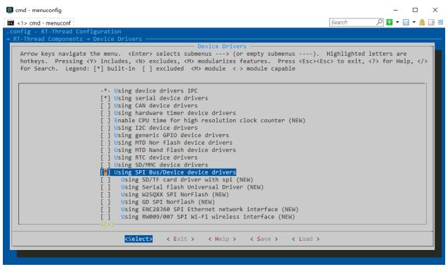
Figure 3.2-1 Using the menuconfig to Start the SPI
Open GPIO driver: Go to RT-Thread Components ---> Device Drivers menu and select Using generic GPIO device drivers. The OLED screen requires two extra GPIOs for the DC and RES signals. The SPI bus driver also needs to operate the chip select pins. All of them need to call the system's GPIO driver interface.
Create a new project and modify the debugging options: Exit the menuconfig configuration interface and save the configuration. Enter the scons --target=mdk5 -s command on the ENV command line to generate the mdk5 project. The new project is named project. Use MDK5 to open the project and modify the debugging options to J-LINK.
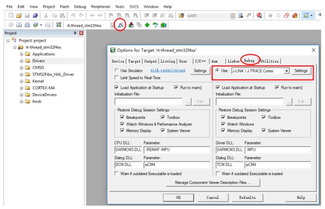
Figure 3.2-2 Modifying the debugging options
Use the list_device command to view the SPI bus: After adding the SPI underlying hardware driver is correct, use the list_device command in the terminal PuTTY (open the corresponding port, the baud rate is configured to 115200) to see the SPI bus. You can also see the UART device and PIN device we use.
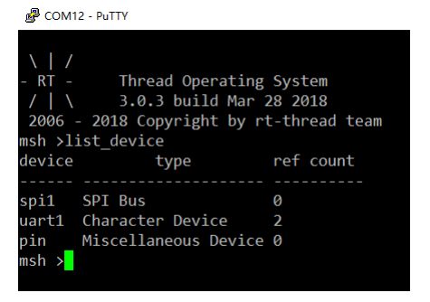
Figure 3.2-3 Using the list_device Command to View System Devices
3.3 Adding Sample Code
Copy the app.c from the SPI device driver sample code to the t-thread\bsp\stm32f4xx-HAL\applications directory. Drv_ssd1351.c and drv_ssd1351.h are copied to the t-thread\bsp\stm32f4xx-HAL\drivers directory and added to the corresponding group in the project. as the picture shows:
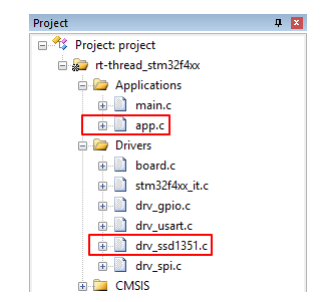
Figure 3.3-1 Adding Sample Code to Project
Calling app_init() in main.c, app_init() creates an oled thread. The thread loops through the rainbow color pattern and the square color pattern.
Main.c calls the test code source as follows:
#include
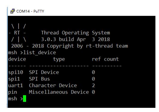
Figure 3.3-2 Using the list_device command to view the SPI device driver
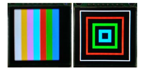
Figure 3.3-3 Experimental phenomenon
4 SPI device driver interface use explain
According to the previous steps, I believe that the reader can quickly run the RT-Thread SPI device driver, then how to use the SPI device driver interface to develop applications?
The RT-Thread SPI device driver usage flow is as follows:
Define the SPI device object and call rt_spi_bus_attach_device() to mount the SPI device to the SPI bus.
Call rt_spi_configure() to configure the SPI bus mode.
Use rt_spi_send() and other related data transmission interfaces to transfer data.
This section will explain in detail the main SPI device driver interface used in the sample code.
4.1 Mounting SPI Devices to the Bus
After the user defines the SPI device object, this function can be called to mount the SPI device to the SPI bus.
Function prototype:
Rt_err_t rt_spi_bus_attach_device(struct rt_spi_device *device, const char *name, const char *bus_name, void *user_data)
| Device | SPI device handle |
| Name | SPI device name |
| Bus_name | SPI bus name |
| User_data | User data pointer |
The function returns: RT_EOK is returned successfully, otherwise an error code is returned.
This function is used to mount an SPI device to the specified SPI bus, register the SPI device with the kernel, and save the user_data to the SPI device device.
note
The user first needs to define the SPI device object device
The recommended SPI bus naming principle is spix, and the SPI device naming principle is spixy. For this example, spi10 indicates device 0 mounted on the spi1 bus.
The SPI bus name can be viewed in the msh shell input list_device command to determine the SPI bus to be mounted by the SPI device.
User_data is typically the CS pin of the SPI device. The SPI controller will operate this pin for chip select when data is transmitted.
This example code in the underlying driver drv_ssd1351.c in rt_hw_ssd1351_config() to mount the ssd1351 device to the SPI bus source is as follows:
#define SPI_BUS_NAME "spi1" / * SPI bus name * / #define SPI_SSD1351_DEVICE_NAME "spi10" / * SPI device name * / ... ... static struct rt_spi_device spi_dev_ssd1351; / * SPI device ssd1351 objects * / static struct stm32_hw_spi_cs spi_cs; / * SPI device chip select pin CS * / ... ... static int rt_hw_ssd1351_config (void) {rt_err_t res; / * oled use PC8 as CS * / spi_cs.pin = CS_PIN; rt_pin_mode (spi_cs.pin, PIN_MODE_OUTPUT) ; /* Set chip select pin to output */res = rt_spi_bus_attach_device(&spi_dev_ssd1351, SPI_SSD1351_DEVICE_NAME, SPI_BUS_NAME, (void*)&spi_cs); if (res != RT_EOK) { OLED_TRACE("rt_spi_bus_attach_device!"); return res; } ... }
4.2 Configuring SPI Mode
After the SPI device is mounted on the SPI bus, the SPI mode and frequency parameters are usually required to meet the clock and data width requirements of different devices.
The mode of the SPI slave device determines the mode of the master device, so the mode of the SPI master device must be the same as that of the slave device.
Function prototype:
Rt_err_t rt_spi_configure(struct rt_spi_device *device, struct rt_spi_configuration *cfg)
| Device | SPI device handle |
| Cfg | SPI transmission configuration parameter pointer |
Function returns: Returns RT_EOK.
This function will save the mode parameter pointed to by cfg to device. This device will use this configuration information when calling the data transfer function.
The struct rt_spi_configuration prototype is as follows:
Struct rt_spi_configuration {rt_uint8_t mode; //spi mode rt_uint8_t data_width; //data width, preferably 8, 16 or 32 bits rt_uint16_t reserved; //reserved rt_uint32_t max_hz; //maximum frequency};
Mode/mode: Use the macro definition in spi.h, including MSB/LSB, master-slave mode, timing mode, etc. The following macro combinations are available.
/* Set the data transmission order to be MSB first or LSB first */ #define RT_SPI_LSB (0<<2) /* bit[2]: 0-LSB */ #define RT_SPI_MSB (1<<2) /* Bit[2]: 1-MSB */ /* Set the master/slave mode of SPI*/ #define RT_SPI_MASTER (0<<3) /* SPI master device */ #define RT_SPI_SLAVE (1<<3) /* SPI slave device */ /* Set clock polarity and clock phase */ #define RT_SPI_MODE_0 (0 | 0) /* CPOL = 0, CPHA = 0 */ #define RT_SPI_MODE_1 (0 | RT_SPI_CPHA) /* CPOL = 0, CPHA = 1 * / #define RT_SPI_MODE_2 (RT_SPI_CPOL | 0) /* CPOL = 1, CPHA = 0 */ #define RT_SPI_MODE_3 (RT_SPI_CPOL | RT_SPI_CPHA) /* CPOL = 1, CPHA = 1 */ #define RT_SPI_CS_HIGH (1<<4) /* chipselect active high * / #define RT_SPI_NO_CS (1 << 5) / * No chipselect * / #define RT_SPI_3WIRE (1 << 6) / * SI / SO pin shared * / #define RT_SPI_READY (1 << 7) / * Slave Pulls low to pause */
Data width/data_width: The data width format that can be sent and received by the SPI master device and SPI slave device is 8-bit, 16-bit, or 32-bit.
Maximum frequency/max_hz: Sets the baud rate of data transmission. It is also set according to the baud rate range of the SPI master device and SPI slave device.
note
This function must be used to configure the SPI device's transfer parameters after mounting the SPI device to the SPI bus.
This example code bottom driver drv_ssd1351.c rt_hw_ssd1351_config () configuration SPI transmission parameters source code is as follows:
Static int rt_hw_ssd1351_config(void) { ... ... /* config spi */ { struct rt_spi_configuration cfg; cfg.data_width = 8; cfg.mode = RT_SPI_MASTER | RT_SPI_MODE_0 | RT_SPI_MSB; cfg.max_hz = 20 * 1000 *1000; /* 20M, SPI max 42MHz, ssd1351 4-wire spi */ rt_spi_configure(&spi_dev_ssdd1, &cfg); } ... ...
4.3 Data Transmission
After the SPI device is mounted on the SPI bus and the related SPI transmission parameters are configured, a series of SPI device driver data transfer functions provided by RT-Thread can be invoked.
Rt_spi_transfer_message()
Function prototype:
Struct rt_spi_message *rt_spi_transfer_message(struct rt_spi_device *device, struct rt_spi_message *message)
| Device | SPI device handle |
| Message | Message pointer |
Function returns: Successfully returned RT_NULL, otherwise returns to the remaining unsent messages
This function can transmit a series of messages. The user can flexibly set the values ​​of various parameters of the message structure so that the data transmission mode can be conveniently controlled.
The struct rt_spi_message prototype is as follows:
Struct rt_spi_message { const void *send_buf; /* send buffer pointer */ void *recv_buf; /* receive buffer pointer */ rt_size_t length; /* send/receive data bytes */ struct rt_spi_message *next; /* point to The pointer to the next message to continue to send */ unsigned cs_take : 1; /* The value is 1, the CS pin is pulled low, the value is 0, the pin state is unchanged */ unsigned cs_release : 1; /* is 1, CS Pin is pulled high, the value is 0, do not change the pin state */ };
SPI is a full-duplex communication bus. It also receives one byte of data while sending one byte of data. The parameter length is the number of data bytes sent/received when data is transmitted once, and the data sent is the buffer pointed to by send_buf. Area data, received data is saved in the buffer pointed to by recv_buf. The value of recv_buf is NULL if the received data is ignored, and the value of send_buf is NULL if the received data is ignored and only data is received.
The parameter next is a pointer to the next message to continue sending. If only one message is sent, the pointer value is set to NULL.
Rt_spi_send()
Function prototype:
Rt_size_t rt_spi_send(struct rt_spi_device *device, const void *send_buf, rt_size_t length)
| Device | SPI device handle |
| Send_buf | Send buffer pointer |
| Length | The number of bytes sent |
Function returns: The number of bytes of data successfully sent
Call this function to send the data of the buffer pointed to by send_buf, ignoring the received data.
This function is equivalent to calling rt_spi_transfer_message() to transfer a message with the message parameter configured as follows:
Struct rt_spi_message msg; msg.send_buf = send_buf; msg.recv_buf = RT_NULL; msg.length = length; msg.cs_take = 1; msg.cs_release = 1; msg.next = RT_NULL;
note
Call this function to send data once. The chip select starts when the data is sent, and the chip selection ends when the function returns.
The code source driver drv_ssd1351.c in the example code in this article calls rt_spi_send() to send instructions and data to SSD1351 as follows:
rt_err_t ssd1351_write_cmd (const rt_uint8_t cmd) {rt_size_t len; rt_pin_write (DC_PIN, PIN_LOW); / * command Low * / len = rt_spi_send (& spi_dev_ssd1351, & cmd, 1); if (! len = 1) {OLED_TRACE ( "ssd1351_write_cmd error .%d",len); return -RT_ERROR; } else { return RT_EOK; } } rt_err_t ssd1351_write_data(const rt_uint8_t data) { rt_size_t len; rt_pin_write(DC_PIN, PIN_HIGH); /* data high*/ len = rt_spi_send( &spi_dev_ssd1351, &data, 1); if (len != 1) { OLED_TRACE("ssd1351_write_data error. %d",len); return -RT_ERROR; } else { return RT_EOK; } }
Rt_spi_recv()
Function prototype:
Rt_size_t rt_spi_recv(struct rt_spi_device *device, void *recv_buf, rt_size_t length)
| Device | SPI device handle |
| Recv_buf | Accept buffer pointer |
| Length | The number of bytes of data received |
The function returns: The number of data bytes successfully accepted
Calling this function will save the received data to the buffer pointed to by recv_buf.
This function is equivalent to calling rt_spi_transfer_message() to transfer a message with the message parameter configured as follows:
Struct rt_spi_message msg; msg.send_buf = RT_NULL; msg.recv_buf = recv_buf; msg.length = length; msg.cs_take = 1; msg.cs_release = 1; msg.next = RT_NULL;
note
Calling this function will accept data once. The chip select starts when the data is received, and the chip selection ends when the function returns.
Rt_spi_send_then_send()
Function prototype:
Rt_err_t rt_spi_send_then_send(struct rt_spi_device *device, const void *send_buf1, rt_size_t send_length1, const void *send_buf2, rt_size_t send_length2);
| Device | SPI bus device handle |
| Send_buf1 | Send buffer 1 data pointer |
| Send_length1 | Send buffer data bytes |
| Send_buf2 | Send buffer 2 data pointer |
| Send_length2 | Send buffer 2 data bytes |
Function returns: RT_EOK successfully returned, otherwise return error code
This function can continuously send 2 buffers of data, ignoring the received data. The chip select starts when send_buf1 is sent, and the chip select ends after sending send_buf2.
This function is equivalent to calling rt_spi_transfer_message() to transfer 2 messages. The message parameter is configured as follows:
struct rt_spi_message msg1, msg2; msg1.send_buf = send_buf1; msg1.recv_buf = RT_NULL; msg1.length = send_length1; msg1.cs_take = 1; msg1.cs_release = 0; msg1.next = & msg2; msg2.send_buf = send_buf2; msg2. Recv_buf = RT_NULL; msg2.length = send_length2; msg2.cs_take = 0; msg2.cs_release = 1; msg2.next = RT_NULL;
Rt_spi_send_then_recv()
Function prototype:
Rt_err_t rt_spi_send_then_recv(struct rt_spi_device *device, const void *send_buf, rt_size_t send_length, void *recv_buf, rt_size_t recv_length);
| Device | SPI bus device handle |
| Send_buf | Send buffer data pointer |
| Send_length | Send buffer data bytes |
| Recv_buf | Receiving buffer data pointer, spi is full-duplex and supports simultaneous sending and receiving |
| Length | Receive buffer data bytes |
Function returns: RT_EOK successfully returned, otherwise return error code
This function sends the first message send_buf start chip select, ignore the received data, then send the second message, the data sent at this time is empty, the received data is saved in recv_buf, the function returns chip select End.
This function is equivalent to calling rt_spi_transfer_message() to transfer 2 messages. The message parameter is configured as follows:
Struct rt_spi_message msg1, msg2; msg1.send_buf = send_buf; msg1.recv_buf = RT_NULL; msg1.length = send_length; msg1.cs_take = 1; msg1.cs_release = 0; msg1.next = &msg2; msg2.send_buf = RT_NULL; msg2. Recv_buf = recv_buf; msg2.length = recv_length; msg2.cs_take = 0; msg2.cs_release = 1; msg2.next = RT_NULL;
The rt_spi_sendrecv8() and rt_spi_sendrecv16() functions encapsulate this function. rt_spi_sendrecv8() sends one byte of data while receiving one byte of data. rt_spi_sendrecv16() sends 2 bytes of data and receives 2 bytes of data.
4.4 SPI Device Driver Application
This example uses SSD1351 to display image information. First, it needs to determine the row and column starting address of the information on the display. Call ssd1351_write_cmd() to send an instruction to SSD1351, and call ssd1351_write_data() to send data to SSD1351. The source code is as follows:
void set_column_address (rt_uint8_t start_address, rt_uint8_t end_address) {ssd1351_write_cmd (0x15); // Set Column Address ssd1351_write_data (start_address); // Default => 0x00 (Start Address) ssd1351_write_data (end_address); // Default => 0x7F (End Address) } void set_row_address(rt_uint8_t start_address, rt_uint8_t end_address) { ssd1351_write_cmd(0x75); // Set Row Address ssd1351_write_data(start_address); // Default => 0x00 (Start Address) ssd1351_write_data(end_address); // Default => 0x7F (End Address } }
5 Reference
All relevant APIs of this article
| Rt_spi_bus_register() | Rt-thread\components\drivers\include\drivers\spi.h |
| Rt_spi_bus_attach_device() | Rt-thread\components\drivers\include\drivers\spi.h |
| Rt_spi_configure () | Rt-thread\components\drivers\include\drivers\spi.h |
| Rt_spi_send_then_send() | Rt-thread\components\drivers\include\drivers\spi.h |
| Rt_spi_send_then_recv() | Rt-thread\components\drivers\include\drivers\spi.h |
| Rt_spi_transfer() | Rt-thread\components\drivers\include\drivers\spi.h |
| Rt_spi_transfer_message() | Rt-thread\components\drivers\include\drivers\spi.h |
| Rt_spi_take_bus() | Rt-thread\components\drivers\include\drivers\spi.h |
| Rt_spi_release_bus() | Rt-thread\components\drivers\include\drivers\spi.h |
| Rt_spi_take() | Rt-thread\components\drivers\include\drivers\spi.h |
| Rt_spi_release() | Rt-thread\components\drivers\include\drivers\spi.h |
| Rt_spi_recv() | Rt-thread\components\drivers\include\drivers\spi.h |
| Rt_spi_send() | Rt-thread\components\drivers\include\drivers\spi.h |
| Rt_spi_sendrecv8() | Rt-thread\components\drivers\include\drivers\spi.h |
| Rt_spi_sendrecv16() | Rt-thread\components\drivers\include\drivers\spi.h |
| Rt_spi_message_append() | Rt-thread\components\drivers\include\drivers\spi.h |
| Ssd1351_write_cmd() | Drv_ssd1351.c |
| Ssd1351_write_data() | Drv_ssd1351.c |
| Rt_hw_ssd1351_config() | Drv_ssd1351.c |
Fiber Fast Connector,Fiber Quick Connector,Fast Connect Fiber Connectors,Fiber Optic Quick Connector
Ningbo Fengwei Communication Technology Co., Ltd , https://www.fengweicommunication.com