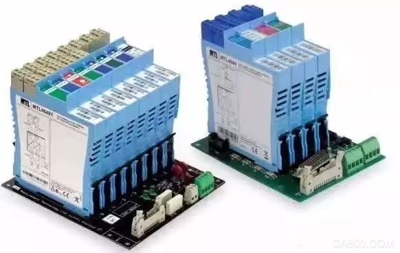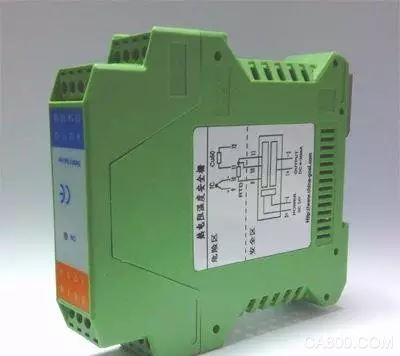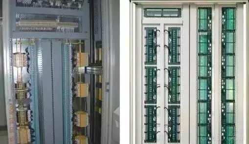
First, the definition of safety barriers and main functions
Safety barriers are also known as safety cages. The safety interface of the intrinsically safe circuit, which can transmit electric signals bidirectionally between the safety zone (intrinsically safe) and the danger zone (non-intrinsically safe), and can limit the energy transfer from the safety zone to the danger zone caused by the fault.
The main function of the barrier is to limit dangerous energy in a safe place from entering a hazardous location and limit the voltage and current to the hazardous location.
Second, the classification of safety barriers
1. Zener safety barrierThe core components of the Zener barrier are Zener diodes, current limiting resistors and fast fuses. Its principle is simple, the circuit is easy to implement, and the price is low. However, due to the defect of its own principle, its reliability in application is greatly affected, and its application range is limited. The reasons are as follows:
(1) The installation location must have a very reliable grounding system, and the grounding resistance of the Zener Barrier must be less than 1Ω, otherwise it will lose the explosion-proof safety protection performance. Obviously such requirements are very harsh and difficult to guarantee in practical engineering applications. .
(2) The Zener barrier has a large impact on the power supply, and it is also prone to damage to the Zener barrier due to power supply fluctuations.
Zener tubes are used to limit the voltage. Compared with the Zener barrier, the isolated barrier has a galvanic isolation function in addition to limiting pressure and current limiting.
2. Isolated barrierIsolated safety barriers are mainly composed of loop energy limiting units, signal and power isolation units, and signal processing units. It not only has the function of limited energy, but also has isolation function, isolated safety barrier, basically has two types of detection end safety barrier and operation end safety barrier.

The detection safety barrier is used together with the two-wire transmitter. Because the isolation barrier adopts measures such as pressure limiting, current limiting, and isolation, it not only prevents dangerous energy from entering the dangerous site from the intrinsically safe terminal, but also improves the intrinsic safety of the system. Performance, but also increased the system's anti-jamming capability, greatly improving the reliability of the system operation. The 24VDC power supply is converted by DC-AC-DC to output the various voltages required by the module circuit.
(1) Principle of Isolated Safety Barrier
The module circuit converts the current or voltage signal input through the intrinsically safe energy limiting circuit to 0.2-1 VDC, and sends it to the module for acquisition, amplification, calculation, and anti-jamming processing, and then modulates the output into an isolated current and voltage by the transformer. The signal is used by the secondary instrument or other instrument behind it. The module also needs to output an isolated 18.5∽28.5VDC voltage and use the intrinsically safe energy limiting circuit as the operating voltage for the two-wire transmitter. The intrinsically safe energy limit circuit can limit the dangerous signal of high current or high voltage into the dangerous scene.
(2) The principle of the operating side isolated safety barrier
After isolating the 4-20mA DC signal output from the regulator or the operator and outputting a 4-20mA DC signal, the intrinsically safe energy limiting circuit is supplied to the electric converter or the on-site electric valve positioner.
Third, select the application advantages of the isolation barrierCompared with zener safety barriers, isolated barriers have higher prices, but many advantages and characteristics still bring users many conveniences, making more and more users prefer to choose isolation barriers.
(1) The use of isolated barriers can effectively isolate the field loop signal in the danger zone from the safe zone loop signal. In this way, the intrinsically safe control system does not require an intrinsically safe grounding system, which simplifies the application of the intrinsically safe explosion-proof system.
(2) The use of isolated barriers greatly enhances the anti-interference ability of the detection and control loops and improves system reliability.
(3) Use an isolated safety barrier to allow grounding of the instrument in the field, allowing the field instrument to be non-isolated.
(4) The isolation barrier has many protection function circuits and is less likely to be damaged accidentally. This allows field instrumentation to be checked for electrification, which can shorten the engineering preparation time and reduce the downtime.
(5) Isolated barriers have strong signal processing capabilities. Such as digital input state control, mV, Pt100 becomes 4 ~ 20mA and so on. This provides greater convenience, reasonableness and effectiveness for the application of field instrumentation and control systems.
(6) When the user applies DCS and ESD at the same time, the two-input safety barrier is selected to effectively isolate the two systems from each other, so as to avoid mutual influence between the systems.
(7) Loop-powered isolated safety barriers not only maintain the advantages of active isolated safety barriers, but also have the same convenient connection of Zener-type safety barriers, and do not require an additional 24V power supply. This is especially suitable for DCS with direct I/O card power supply. system.
(1) Check whether the instrument power supply access is correct and reliable.
(2) Check that the power supply voltage is normal.
(3) Check whether the 24V power supply is reversed.
2. Output no signal(1) Whether the input signal is correctly connected to the input terminal.
(2) Whether the input signal type is the same as the instrument input type.
(3) Whether the output terminal is tight.
(4) Whether the removable external terminals are plugged into place.
(5) The external output circuit is open circuit.
3. Large deviation of output value(1) Whether the positive and negative leads are reversed when the thermocouple is input.
(2) Whether the three-wire connection is correct when the thermal resistance is input.
(3) Check whether the positive and negative polarities of the output wiring are reversed.
(4) Whether the sum of the external load resistance is greater than the specified ohm (at 4-20mA output) during current output.
(5) When the voltage output, external load resistance is less than 500 kiloohms.
(6) The power supply voltage is too low.
4. The output signal is not stable(1) Check if the wiring is firm.
(2) Check if the input signal is stable.
(3) Check if the output circuit wiring is reliable.
(4) Check whether there is high-power electromagnetic equipment around the instrument.

Perimeter LED Display,LED Perimeter Boards,Stadium Perimeter LED Display,LED Perimeter Advertising Systems
ShenZhen UHLED Technology Co., LTD. , https://www.uhled.com