introduction
With the continuous improvement of people's living standards, the problem of home security has become more prominent. Traditional mechanical locks have been gradually eliminated due to their simple structure and poor safety. Electromagnetic locks have gradually entered thousands of households due to their high confidentiality, use of the words, and high safety factor. If there are multiple doors in a home system, a comprehensive door control system is required so that all door switches can be monitored.
The gate control system designed by reference is based on AT89S51 single-chip microcomputer. The system has large power consumption and high cost of use, so its application has certain limitations. The gated system designed by reference uses the local area network for network control, so the production cost is high and the application range is limited. In view of the above shortcomings, the system adopts MSP430 series MCU CCA30F5135 chip as the control core, which not only has the low power consumption performance of MSP430 series MCU, but also has the function of RF wireless transceiver. RF wireless function can realize wireless control of the door, which is convenient for users. And the low power consumption makes the use cost lower and meets the requirements of current applications.
1 door control system operation principle
The system is mainly composed of two parts: one part is the central control center, which is mainly used as the management center, the user can monitor the switch status of all the doors; the other part is the door control module, whose function is mainly to control the switch of the door, and the switch of the door Information is transmitted to the central control center, including keyboard circuits, display circuits, alarm circuits, and unlock control circuits. The overall block diagram of the system is shown in Figure 1.
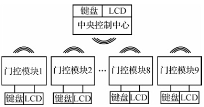
Figure 1 system overall block diagram
The system uses an electronic password lock to control the switch door. The electronic code lock has a lower cost than the RF card, and the password can be changed at any time, and the security is high. When you need to open the door, first enter the 6-digit password from the matrix keyboard. The initial password is set by the program. After entering the password, press the open button to unlock. If you want to clear the input, press the cancel button. When you press the button, there will be a “short dropâ€. Sound prompt. If the entered password is correct, the password input correct indicator is on, the LCD displays “Password correctâ€, and a signal to turn on the electromagnetic lock is output; if the password is entered incorrectly, the password input error indicator is on, and the LCD displays “Password Errorâ€. If there is no operation for 6 s, all input is cleared. If a gate module has a password input condition, the CC430F5135 microcontroller inside the gate module transmits the signal of the person entering the password to the central control center through the internal integrated RF wireless transceiver, so that the central control center can know all the buildings. In the case of the door, the central control center displays all the door switch conditions via an LCD. If the user wants to open or close a door, he only needs to find the door number through the keyboard and enter the relevant instructions. Both the gate module and the central control center use CC430F5135 as the control core. If there is no operation after 40 s, the microcontroller will enter the low power mode.
2 system hardware design
The hardware design of the access control system includes the design of the central control center and the design of the gating module. The following sections describe each part in detail.
2.1 Central Control Center Design
The central control center and the gate control module are based on the MSP430 series single-chip microcomputer CC430F5135. The integrated RF wireless module saves the externally extended wireless communication module and reduces the cost. The CC430F5135 is a combination of TI's MSP430F5xx MCUs and low-power RF transceivers for extremely low current consumption, enabling battery-powered wireless networking applications to operate for up to 10 years without maintenance; The advanced functionality included also provides the core power for an innovative RF sensor network to report data to a central collection point. The CC430F5135 is a 16-bit ultra-low-power MCU with 16 KB of flash, 2 KB of RAM, CC1101 radio transceiver, AES-128 and USCI. The supply voltage is 1.8 to 3.6 V. The normal operating mode consumes 160 μA. /MHz, low power mode 3 consumes 2.0μA.
2.1.1 RF430 Transceiver Module Peripheral Circuit of CC430F5135
The CC430F5135 integrates the CC1101 radio transceiver. The RF frequency of this system is set to 315 MHz, the channel spacing is 540 kHz, and the data transmission rate is 250 kbps. In the design of this system, the transmission power can reach up to -96 dBm. In practical applications, the transmission power can be set according to the distance of the transmission distance, so that the power consumption can be minimized. Its circuit is shown in Figure 2. The power supply for the CC430F5135 is two No. 5 batteries with a voltage of +3 V and an external crystal of 26 MHz. RF_N and RF_P are RF radio transmit pins. Two-pin external antennas can achieve a power of -96 dBm and a transmission distance of up to 200 m.
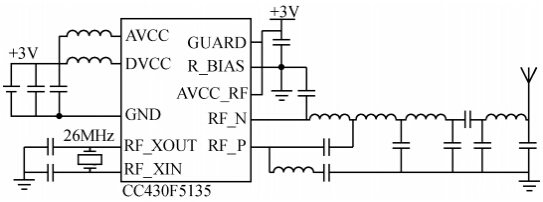
Figure 2 CC430F5135 RF wireless transceiver module peripheral circuit
2.1.2 LCD display module
Considering the low power requirements of the device, the selected display module must achieve low power consumption. This system adopts LCD12864 as the display module. Its power supply voltage is 4.5~5 V, the working current is 3 mA, low power consumption, long life and high reliability. The module has two LCD driver chips, which control the left and right areas of the display respectively. Each driver chip has 512 bytes of RAM. The hardware connection diagram of CC430F5135 is shown in Figure 3. The LCD12864 is powered by +5V, and the +3V voltage is converted to +5 V by the booster chip and supplied to the LCD12864. The P1 port of the MCU is used as the control port for controlling the LCD 12864, and the P2 port is used as the data port to communicate with the LCD 12864. Because the output voltage of the CC430F5135 port is +3 V, and the port voltage of the LCD12864 is +5 V, the ports of the two cannot be directly connected, so a voltage conversion chip is needed to solve the voltage mismatch problem. This system uses TI's dual-voltage power supply bidirectional driver SN74 ALVCA24_5 to achieve level conversion, one side is 3 V, the other side is 5 V, which better solves the conversion problem of 3 V and 5 V level.
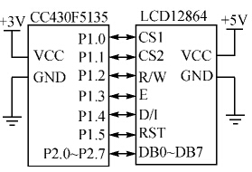
Figure 3 CC430F5135 and LCD12864 interface circuit
2.1.3 4&TImes; 4 matrix keyboard hardware circuit
4 & TImes; 4 matrix keyboard hardware circuit diagram shown in Figure 4. This system uses the interrupt mode to determine the input of the button, because the P0 port inside the CC430F5135 can be regarded as an external interrupt port, so if any one of the buttons is pressed, then the level of the two ports will be abrupt. So, according to the internal preset program, you can know which key is pressed. The keyboard has numeric keys and function keys, the numeric keys are used for password input, and the function keys have a cancel key, a confirm key, a left shift key, a right shift key, an open key and a close key. The cancel button is used to delete the entered password, the confirmation button is used to determine the correct input, and the open button and the close button are used to open and close the door. When the fire control center needs to switch a certain door, you can press the left shift key or the right shift key to select the door number to be switched. After the selection is successful, press the open key or close the door to open and close the door.
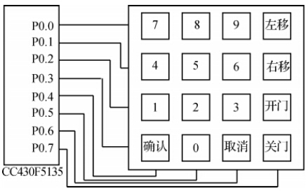
Figure 4 4 ​​× 4 matrix keyboard hardware circuit
2.2 Door control module design
The door control module includes the RF wireless transceiver module circuit of CC430F5135, LCD hardware circuit, keyboard hardware circuit, relay drive door hardware circuit and buzzer indicator hardware circuit. The CC430F5135's RF wireless transceiver module circuit, LCD hardware circuit and keyboard hardware circuit are basically the same as the central control center design, and will not be introduced here. The following mainly introduces the buzzer indicator hardware circuit and the relay drive door hardware circuit.
2.2.1 Buzzer indicator hardware circuit
As shown in Figure 5, the CC430F5135 controls the turn-on and turn-off of the triac to control the turn-on and turn-off of the buzzer to achieve the purpose of the indication. The P3.0, P3.1, and P3.2 ports of the CC430F5135 microcontroller control the turn-on or turn-off of the transistor 8050 by controlling the high and low levels of the output signal, thereby achieving the corresponding functions. If the P3.0 port is high and the triode is turned on, the buzzer will sound. If P3.1 and P3.2 are set high, the red or green indicator will light. The red indicator light is used to warn the password input error, the green indicator light indicates that the password is entered correctly, and the door will open.
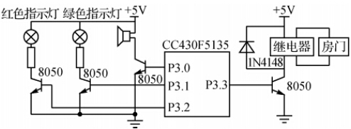
Figure 5 buzzer indicator and relay drive door hardware circuit
2.2.2 Relay drive door hardware circuit
The function of this circuit is to automatically open or close the door when the password is entered correctly and the door open button or door close button is pressed. The system uses CC430F5135 to control the opening of the relay, and then controls the operation of the rotating motor to control the action of the door. In order to ensure stable and reliable operation of the relay, HJR-3FF-S series relays are selected. The relay load voltage can be applied to 250 V (AC) / 30 V (DC), and can work more than 1 × 10⁵ times at an ambient temperature of -30 ~ +60 ° C. Its rated working voltage is +5 V, and the rated working current is up to 70 mA. Because the I/O output of CC430F5135 is +3 V, it can't directly drive the relay. It needs to add a triode 8050 as a switch to control the relay's switch. The corresponding control action is completed by receiving the control information of the CC430F5135.
KN95 Protecive face masks adopt the GB2626-2006 standard, which stipulated the production and technical specifications of respirators .there is strict requirements on materials, structure, appearance, performance, filtration efficiency , breath resistance, test methods, product identification and packaging.
Protective Face Mask,Anti-particulate Protective Mask,Face Mask KN95,Non Medical Face Mask
Jilin Province Wanhe light Co.,Ltd , https://www.wanhelight.com