ã€Abstract】The construction of a digital monitoring and data acquisition system SCADA (Sué„„pervisoryControlandDataAcquisiTIon) based on Modbus protocol was proposed for a dynamic model laboratory transformation. The whole system takes SLC/505PLC as the core, and the PM170 instrument supporting Modbus protocol is used as the measurement unit, and then the data is transmitted to the GP touch screen as the human-machine interface through Ethernet. The actual operation in the past year after the completion of the transformation shows that the entire monitoring system is stable, reliable and efficient, and can fully meet the needs of teaching and research.
As a physical simulation of the actual large power system, the dynamic simulation laboratory must not only conform to the various normal operating modes of the actual power system, but also simulate various fault modes of the power system; not only to provide accurate and detailed measurement data for scientific research, but also It is necessary to ensure that all test equipment is always running in the allowed state. These all put forward high requirements for the monitoring and control system of the power system dynamic simulation laboratory.
This paper introduces a SCADA (Supervisory Control and DataAcquisiTIon) system for monitoring the entire dynamic model system. The monitoring system is constructed by using Prosoft's 3150-MCM data acquisition module and ABB's PM170 series meter to form the Modbus network to measure the operating parameters of the system. And the acquisition, the data is processed and calculated by AB's SLC/505PLC, and then sent to the GP touch screen as the upper computer through Ethernet.
1. Introduction to Modbus ProtocolThe Modbus protocol is an industrial communication and distributed control system protocol developed by Modicon. A Modbus network is a master-slave network that allows one host to communicate with one or more slaves. It uses the command/response mode, and each command message corresponds to a response message. The command message is sent by the host. When the slave receives the message sent to itself, it sends a corresponding response message to respond. Each slave in the network must be assigned a unique address. The command issued by the host contains the slave address that requires access. Only the slave with this address will respond to the command.
Both the RTU and ASCII transmission modes are used in the Modbus protocol. The transmission format of the RTU mode is 8 data bits, 2 stop bits, and no parity bit. The RTU receiving device determines the start of a frame by the elapsed time between receiving characters. If there are no new characters or no completed frames after 3 and a half characters, the receiving device will give up the frame and set the next character as new. The beginning of a frame. In the RTU mode, 1-byte information is transmitted as an 8-bit character; in the ASCII mode, it is transmitted as two ASCII characters. For example, when "08" is transmitted, it is "00001000" when RTU mode is used, but when it is ASCII mode, it is "00110000" + "00111000" ("0" and "8" of ASCII characters). Therefore, when transmitting the same data, the efficiency of the RTU mode is approximately twice that of the ASCII mode, and the RTU mode is generally adopted.
2, 3150-MCMModbus communication module introductionThe 3150-MCM communication module is a Modbus communication card produced by Prosoft to cooperate with Allen-Bradley's SLC500 series PLC. It has two serial ports, each of which can support RS-232, RS-422, RS-485 communication protocol. (selected by jumpers on the module). The two serial ports of the module can be configured such that both are Master or both are Slave; either one is Master and the other is Slave.
Used as a Master in this application. The function of the 3150-MCM communication module is relatively powerful. It has up to 100 command lists inside. For each command, the slave address, the first address of the internal addressing, and the number of bytes requested to be accessed are configurable to form a command message conforming to the Modbus protocol. There are up to 4000 16-bit memories inside the module that can be used to store data and exchange data with the CPU unit of the PLC. In the event of a communication error, the module can generate an error code and return it to the PLC for error handling. There are many commands in the Modbus protocol. The 3150-MCM module does not support all of the commands, but only chooses to implement the most important commands. For general engineering applications, these commands are sufficient.
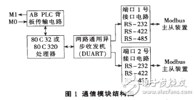
The 3150-MCM module is installed in the rack of the PLC and communicates with the CPU unit through the backplane. Since the SLC does not have a true block communication function, the I/Otable is used to control the handshake between the module and the CPU, and the data is transmitted using the M0/M1 file. The structure of the module communication part is shown in Figure 1.

After power-on, the module initializes first, and then continuously requests the CPU unit to request configuration data until a data block containing configuration data is obtained. After that, the module enters the normal working process, including managing the communication of the two serial ports and exchanging information with the CPU unit.
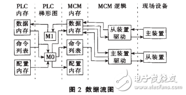
From the perspective of the data stream, the module is equivalent to the middle layer between the PLC and the external device. It communicates with external devices via the Modbus network on the one hand, and communicates with the CPU unit using M0/M1 files on the other hand, as shown in Figure 2.

ABB's PM170 series of power meters is a new generation of measuring instruments developed by ABB to adapt to the power industry. It has simple and flexible wiring, no need for DC transmitter, and can be directly connected to TV and TA. It is equipped with a microprocessor inside, and can measure three kinds of electrical quantities such as three-phase voltage, current, active power, reactive power, power factor, frequency and unbalanced current. At the same time, it has a relatively powerful communication function: it supports RS-232, RS-422 and RS-485 communication interfaces on the physical interface; it supports ASCII, Modbus and DNPV3.00 protocols in communication protocol.
Displacement sensor, also known as linear sensor, is a linear device belonging to metal induction. The function of the sensor is to convert various measured physical quantities into electricity. In the production process, the measurement of displacement is generally divided into measuring the physical size and mechanical displacement. According to the different forms of the measured variable, the displacement sensor can be divided into two types: analog and digital. The analog type can be divided into two types: physical property type and structural type. Commonly used displacement sensors are mostly analog structures, including potentiometer-type displacement sensors, inductive displacement sensors, self-aligning machines, capacitive displacement sensors, eddy current displacement sensors, Hall-type displacement sensors, etc. An important advantage of the digital displacement sensor is that it is convenient to send the signal directly into the computer system. This kind of sensor is developing rapidly, and its application is increasingly widespread.
Displacement Transducer,Linear Displacement Transducer,Linear Variable Differential Transducer,Linear Variable Displacement Transducer
Changchun Guangxing Sensing Technology Co.LTD , https://www.gx-encoder.com