Overview:
The high-power high-frequency switching power supply based on DSP introduced in this paper fully utilizes the powerful functions of DSP, can control the switching power supply in many aspects, and can simplify the device, reduce the cost, reduce the power consumption, and improve the reliability of the device.
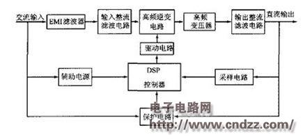
1. Overall scheme of power supply The basic component block diagram of the switching power supply designed in this paper is shown in Figure 1. It is mainly composed of power main circuit, DSP control loop and other auxiliary circuits.
The main advantage of switching power supplies is at "high frequencies." Filter inductors, capacitors, and transformers typically account for a large percentage of the size and weight of the power supply unit. From the knowledge of "circuit" and "motor science", increasing the switching frequency can reduce the parameters of the filter and miniaturize the transformer, thereby effectively reducing the size and weight of the power supply unit. Taking a transformer with a core as an example, the analysis is as follows: 
Figure 1 system composition block diagram
2. The hardware design of the system The main circuit of the power supply adopts the structure of “AC-DC-AC-DC†conversion, which is mainly composed of input grid EMI filter, input rectifier filter circuit, high frequency inverter circuit, high frequency transformer and output. The rectifier filter circuit is composed of several parts, as shown in Figure 2. 
Figure 2 Power main circuit schematic diagram The basic working principle is: AC input voltage is EMI filtered, rectified and filtered to obtain DC voltage, DC voltage is converted into high-frequency AC voltage by high-frequency inverter, and then isolated by high-frequency transformer The desired high-frequency AC voltage is output, and finally, the output rectification and filtering circuit is used to rectify and filter the high-frequency AC voltage outputted by the high-frequency transformer to obtain the required high-quality, high-quality DC voltage. Figure 3 shows the voltage waveform conversion process for each link of the AC input voltage to the final output DC voltage.
(Please read the PDF for details)
5.1 Column Speaker,Column Array Speakers,Column Speakers,Column Speaker System
GUANGZHOU SOWANGNY ELECTRONIC CO.,LTD , https://www.jerry-power.com