The Butterworth filter is a type of electronic filter. The Butterworth filter is characterized by the smoothest frequency response curve of the passband. This filter was first proposed by a British engineer, Stephen Butterworth, in a paper published in the British Journal of Radio Engineering in 1930.
Number of Butterworth filtersThe method of designing an analog filter according to a given parameter, and then performing a variable transformation to obtain a digital filter is called an indirect design of the filter. An analog filter that is the basis of the design of a digital filter is called a prototype filter. Here, we first introduce the simplest and most basic prototype filter, Butterworth low-pass filter. Since the IIR filter does not have linear phase characteristics, it is not necessary to consider the phase characteristics and directly consider its amplitude characteristics.

Here, N is the number of times the filter, and Ωc is the cutoff frequency. As can be seen from the amplitude characteristics of the above equation, this is a monotonically decreasing function whose amplitude characteristic is that there is no ripple. When designing, it is generally necessary to first calculate the number N that matches the required design parameters. First, you need to calculate the stopband attenuation from the stopband frequency first.

Bring the amplitude characteristics of the Butterworth low-pass filter directly into the upper form, then
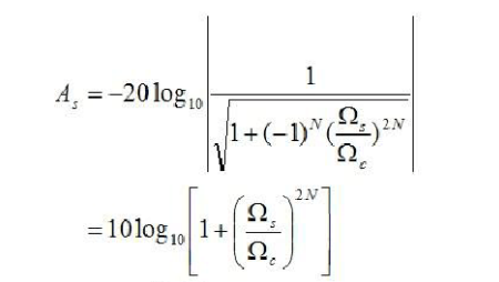
Finally, the number of times N can be solved is
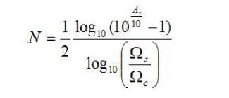
Of course, N here can only be a positive number, so if the result is a decimal, discard the decimal and round up.
Transfer function of Butterworth filterThe transfer function of the Butterworth low-pass filter can be obtained from the denominator polynomial of its amplitude characteristic. Denominator polynomial
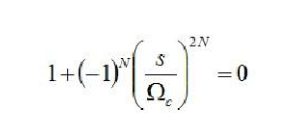
According to S, the pole can be obtained. Here, in order to facilitate the processing, we divide the equation into two cases. When N is even,
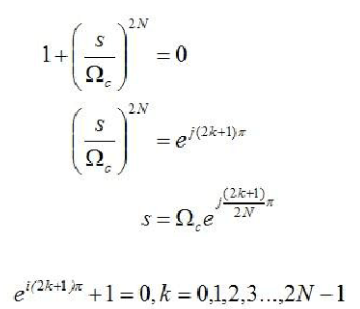
Here, the Euler formula is used. Similarly, when N is odd,
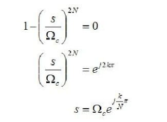
Similarly, the Euler formula is also used here. Inductive above, the solution of the pole is

The poles obtained by the above equation are points equally spaced on a circle having a radius of Ωc in the s-plane, and the number is 2N. In order to stabilize its IIR filter, only the points whose poles are in the left half plane of the S plane can be selected. After the stable pole is selected, the transfer function of the analog filter can be obtained by the following equation.
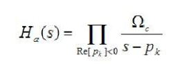
First of all, it is the calculation of the number of times. The calculation of the number of times can be obtained by the following formula.
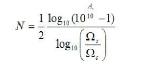
Its corresponding C language program is
N = Ceil(0.5*( log10 ( pow (10, Stopband_attenuaTIon/10) - 1) /
Log10 (Stopband/Cotoff) ));
Then there is the choice of the pole. Here we have to declare a complex structure because of the complex operations involved. Most importantly, the calculation of the pole contains a natural exponential function, which is not very convenient for computers, so we replace it with a trigonometric function.

In this case, the real part and the imaginary part can also be calculated separately. Its code is implemented as
Typedef struct
{
Double Real_part;
Double Imag_Part;
} COMPLEX;
COMPLEX poles[N];
For(k = 0;k <= ((2*N)-1) k++)
{
If(Cotoff*cos((k+dk)*(pi/N)) < 0)
{
Poles[count].Real_part = -Cotoff*cos((k+dk)*(pi/N));
Poles[count].Imag_Part= -Cotoff*sin((k+dk)*(pi/N));
Count++;
If (count == N) break;
}
}
Submersible Pump,Solar Pump Series,48V Dc Solar Pump,Submersible Dc Solar Water Pumps
Wuxi Doton Power , http://www.dotonpower.com