One. AD schematic to OrCAD schematic
AD version to use AD6.9, AD9 can not, there will be errors when saving, the steps are as follows:
1. Build a project with only schematics.
2. Save as OrCAD (.dsn) project. As shown below:
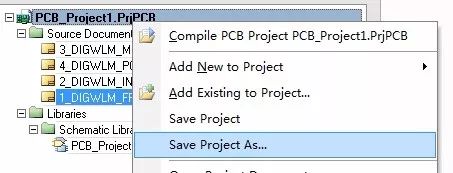
Save as

Select OrCAD format
3. Use Capture to open the saved DSN file. When it opens, it will wait for a while, and the size of the schematic will be longer.
4. Note: the size of the schematic can not be too large, the schematic size in A3 or A3 below the turn out is better, too large Zhang will appear device loss. Small size will also cause minor problems, such as device misalignment, and generally there will be misalignment between resistors and capacitors. I estimate that the library referenced by the same type of device used in the AD schematic is not the same.
II. Principle of AD Gallery to OrCAD Principle Gallery
Proceed as follows:
1. First derive the principle library of the AD in the AD schematic diagram. If there is already a schematic library, you do not need to export it.
Open the project with the schematic, menu command: Design => Make Schematic Library
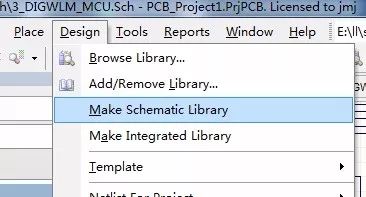
2. Save as a library file in OrCAD format
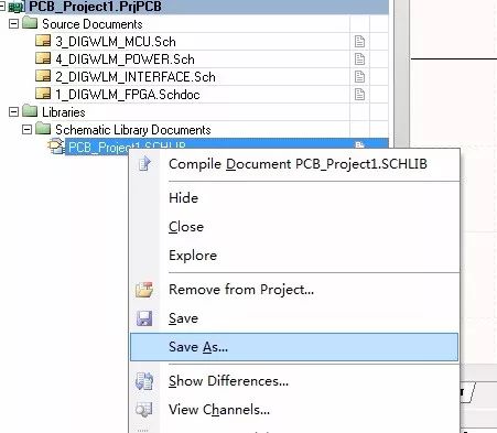
Save as

Select OrCAD Format Library File
3 can be directly opened with Capture
4. Note: When the AD principle library is transferred to the OrCAD principle library, the AD version is not required. I have tried both AD6.9 and AD9.
3. AD PCB package transferred to Allegro package or AD PCB to Allegro PCB.
When the AD package is transferred to the ALLEGRO package, all packages are placed on one PCB or placed on the PCB in batches. The PCB is converted to ALLEGRO format, and then the PCB is packaged using ALLEGRO.
Proceed as follows:
1. Import AD format PCB directly with PADS Layout (PADSVX.0)
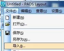
Import
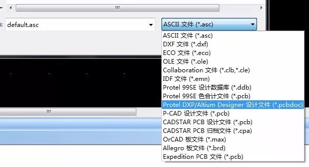
Select AD format PCB
2. PADS Layout (PADSVX.0) Export ASCII Files (*.asc)
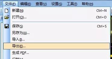
Export
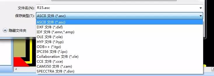
Select Export ASCII File (*.asc)
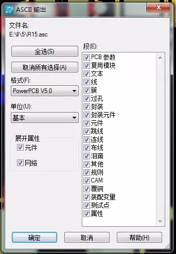
The ASCII options are shown above. The format is optional from Power PCB V3.0 to V5.0, and PADS Layout9.3 or later.
3. Import the ASCII file (*.asc) into ALLEGRO. ALLEGRO uses the V16.6 version. Other versions have not.
as follows:
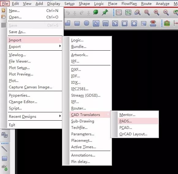
Select import PADS format file
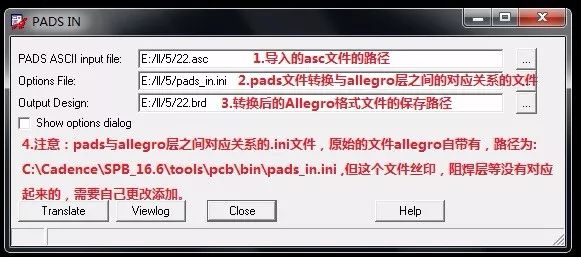
Import and convert output file path selection, and layer configuration file selection.
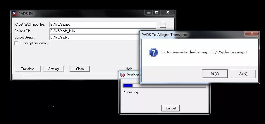
Pressing Convert will pop up this window and confirm with “Yesâ€.
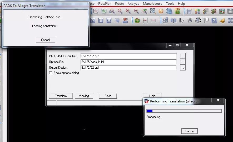
A window pops up in the upper left corner, waiting for it to complete.
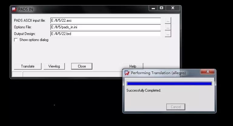
Conversion complete and successful
4. Use Allegro to open the file you just converted and saved
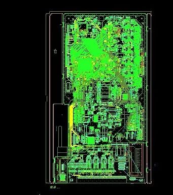
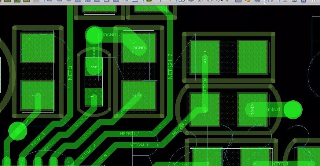
Both silkscreen and solder mask are available.
5.Allegro PCB Packaging Method everywhere: Execute the menu command: File => Export => Librarys
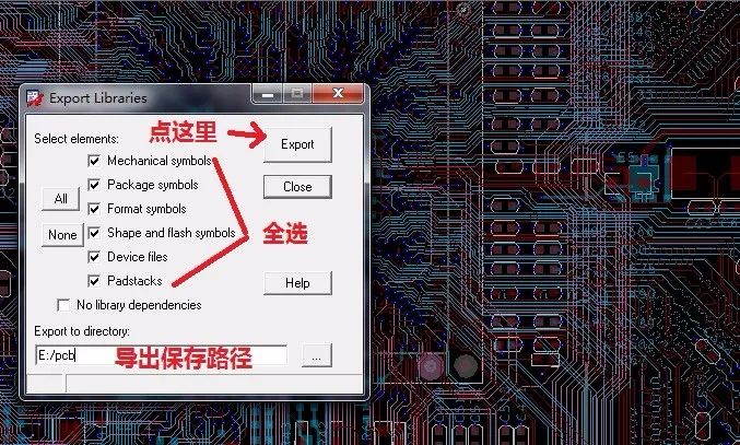
6. Insufficient: The converted layer configuration file, after the layer is configured, there are still some solder mask pads and stencil layers not coming out. Need to be improved by hand.
7.ini layer configuration file description:
Allegro comes with the original file types as follows:
[Options]
CreateSolderLayers=0
SolderOversize=0
[Line Map]
0=BOARD GEOMETRY|ALL
1=ETCH|TOP
2=ETCH|INTERNAL1
3=ETCH|INTERNAL2
4=ETCH|INTERNAL3
5=ETCH|INTERNAL4
6=ETCH|BOTTOM
7=UNUSED|-
8=UNUSED|-
9=UNUSED|-
10=UNUSED|-
11=UNUSED|-
12=UNUSED|-
13=UNUSED|-
14=UNUSED|-
15=UNUSED|-
16=UNUSED|-
17=UNUSED|-
18=UNUSED|-
19=UNUSED|-
20=UNUSED|-
21=UNUSED|-
22=UNUSED|-
23=UNUSED|-
24=UNUSED|-
25=UNUSED|-
26=UNUSED|-
27=UNUSED|-
28=UNUSED|-
29=UNUSED|-
30=UNUSED|-
[Copper Map]
0=BOARD GEOMETRY|ALL
1=ETCH|TOP
2=ETCH|INTERNAL1
3=ETCH|INTERNAL2
4=ETCH|INTERNAL3
5=ETCH|INTERNAL4
6=ETCH|BOTTOM
7=UNUSED|-
8=UNUSED|-
9=UNUSED|-
10=UNUSED|-
11=UNUSED|-
12=UNUSED|-
13=UNUSED|-
14=UNUSED|-
15=UNUSED|-
16=UNUSED|-
17=UNUSED|-
18=UNUSED|-
19=UNUSED|-
20=UNUSED|-
21=UNUSED|-
22=UNUSED|-
23=UNUSED|-
24=UNUSED|-
25=UNUSED|-
26=UNUSED|-
27=UNUSED|-
28=UNUSED|-
29=UNUSED|-
30=UNUSED|-
[Text Map]
0=BOARD GEOMETRY|ALL
1=ETCH|TOP
2=ETCH|INTERNAL1
3=ETCH|INTERNAL2
4=ETCH|INTERNAL3
5=ETCH|INTERNAL4
6=ETCH|BOTTOM
7=UNUSED|-
8=UNUSED|-
9=UNUSED|-
10=UNUSED|-
11=UNUSED|-
12=UNUSED|-
13=UNUSED|-
14=UNUSED|-
15=UNUSED|-
16=UNUSED|-
17=UNUSED|-
18=UNUSED|-
19=UNUSED|-
20=UNUSED|-
21=UNUSED|-
22=UNUSED|-
23=UNUSED|-
24=UNUSED|-
25=UNUSED|-
26=UNUSED|-
27=UNUSED|-
28=UNUSED|-
29=UNUSED|-
30=UNUSED|-
[Decal Map]
0=PACKAGE GEOMETRY|SILKSCREEN_TOP
1=PACKAGE GEOMETRY|SILKSCREEN_TOP
2=UNUSED|-
3=UNUSED|-
4=UNUSED|-
5=UNUSED|-
6=UNUSED|-
7=UNUSED|-
8=UNUSED|-
9=UNUSED|-
10=UNUSED|-
11=UNUSED|-
12=UNUSED|-
13=UNUSED|-
14=UNUSED|-
15=UNUSED|-
16=UNUSED|-
17=UNUSED|-
18=UNUSED|-
19=UNUSED|-
20=UNUSED|-
21=UNUSED|-
22=UNUSED|-
23=UNUSED|-
24=UNUSED|-
25=UNUSED|-
26=UNUSED|-
27=UNUSED|-
28=UNUSED|-
29=UNUSED|-
30=UNUSED|-
[Pad Map]
0=ETCH|internal_pad_def
1=ETCH|TOP
2=ETCH|INTERNAL1
3=ETCH|INTERNAL2
4=ETCH|INTERNAL3
5=ETCH|INTERNAL4
6=ETCH|BOTTOM
7=UNUSED|-
8=UNUSED|-
9=UNUSED|-
10=UNUSED|-
11=UNUSED|-
12=UNUSED|-
13=UNUSED|-
14=UNUSED|-
15=UNUSED|-
16=UNUSED|-
17=UNUSED|-
18=UNUSED|-
19=UNUSED|-
20=UNUSED|-
21=UNUSED|-
22=UNUSED|-
23=UNUSED|-
24=UNUSED|-
25=UNUSED|-
26=UNUSED|-
27=UNUSED|-
28=UNUSED|-
29=UNUSED|-
30=UNUSED|-
[Via Map]
0=VIA CLASS|internal_pad_def
1=VIA CLASS|TOP
2=VIA CLASS|INTERNAL1
3=VIA CLASS|INTERNAL2
4=VIA CLASS|INTERNAL3
5=VIA CLASS|INTERNAL4
6=VIA CLASS|BOTTOM
7=UNUSED|-
8=UNUSED|-
9=UNUSED|-
10=UNUSED|-
11=UNUSED|-
12=UNUSED|-
13=UNUSED|-
14=UNUSED|-
15=UNUSED|-
16=UNUSED|-
17=UNUSED|-
18=UNUSED|-
19=UNUSED|-
20=UNUSED|-
21=UNUSED|-
22=UNUSED|-
23=UNUSED|-
24=UNUSED|-
25=UNUSED|-
26=UNUSED|-
27=UNUSED|-
28=UNUSED|-
29=UNUSED|-
30=UNUSED|-
My own changed layer profile is as follows:
[Options]
CreateSolderLayers=0.0254 Here I changed and found no change
SolderOversize=0.0254 Here I changed and found no change
[Line Map]
0=BOARD GEOMETRY|ALL
1=ETCH|TOP
2=ETCH|INTERNAL1
3=ETCH|INTERNAL2
4=ETCH|INTERNAL3
5=ETCH|INTERNAL4
6=ETCH|BOTTOM
7=UNUSED|-
8=UNUSED|-
9=UNUSED|-
10=UNUSED|-
11=UNUSED|-
12=UNUSED|-
13=UNUSED|-
14=UNUSED|-
15=UNUSED|-
16=UNUSED|-
17=UNUSED|-
18=UNUSED|-
19=UNUSED|-
20=UNUSED|-
21=PACKAGE GEOMETRY|SOLDERMASK_TOP
22=PACKAGE GEOMETRY|PASTEMASK_BOTTOM
23=PACKAGE GEOMETRY|PASTEMASK_TOP
24=UNUSED|-
25=UNUSED|-
26=PACKAGE GEOMETRY|SILKSCREEN_TOP
27=UNUSED|-
28=PACKAGE GEOMETRY|SOLDERMASK_BOTTOM
29=PACKAGE GEOMETRY|SILKSCREEN_BOTTOM
30=UNUSED|-
[Copper Map]
0=BOARD GEOMETRY|ALL
1=ETCH|TOP
2=ETCH|INTERNAL1
3=ETCH|INTERNAL2
4=ETCH|INTERNAL3
5=ETCH|INTERNAL4
6=ETCH|BOTTOM
7=UNUSED|-
8=UNUSED|-
9=UNUSED|-
10=UNUSED|-
11=UNUSED|-
12=UNUSED|-
13=UNUSED|-
14=UNUSED|-
15=UNUSED|-
16=UNUSED|-
17=UNUSED|-
18=UNUSED|-
19=UNUSED|-
20=UNUSED|-
21=PACKAGE GEOMETRY|SOLDERMASK_TOP
22=PACKAGE GEOMETRY|PASTEMASK_BOTTOM
23=PACKAGE GEOMETRY|PASTEMASK_TOP
24=UNUSED|-
25=UNUSED|-
26=PACKAGE GEOMETRY|SILKSCREEN_TOP
27=UNUSED|-
28=PACKAGE GEOMETRY|SOLDERMASK_BOTTOM
29=PACKAGE GEOMETRY|SILKSCREEN_BOTTOM
30=UNUSED|-
[Text Map]
0=BOARD GEOMETRY|ALL
1=ETCH|TOP
2=ETCH|INTERNAL1
3=ETCH|INTERNAL2
4=ETCH|INTERNAL3
5=ETCH|INTERNAL4
6=ETCH|BOTTOM
7=UNUSED|-
8=UNUSED|-
9=UNUSED|-
10=UNUSED|-
11=UNUSED|-
12=UNUSED|-
13=UNUSED|-
14=UNUSED|-
15=UNUSED|-
16=UNUSED|-
17=UNUSED|-
18=UNUSED|-
19=UNUSED|-
20=UNUSED|-
21=PACKAGE GEOMETRY|SOLDERMASK_TOP
22=PACKAGE GEOMETRY|PASTEMASK_BOTTOM
23=PACKAGE GEOMETRY|PASTEMASK_TOP
24=UNUSED|-
25=UNUSED|-
26=PACKAGE GEOMETRY|SILKSCREEN_TOP
27=UNUSED|-
28=PACKAGE GEOMETRY|SOLDERMASK_BOTTOM
29=PACKAGE GEOMETRY|SILKSCREEN_BOTTOM
30=UNUSED|-
[Decal Map]
0=PACKAGE GEOMETRY|SILKSCREEN_TOP
1=PACKAGE GEOMETRY|SILKSCREEN_TOP
2=UNUSED|-
3=UNUSED|-
4=UNUSED|-
5=UNUSED|-
6=UNUSED|-
7=UNUSED|-
8=UNUSED|-
9=UNUSED|-
10=UNUSED|-
11=UNUSED|-
12=UNUSED|-
13=UNUSED|-
14=UNUSED|-
15=UNUSED|-
16=UNUSED|-
17=UNUSED|-
18=UNUSED|-
19=UNUSED|-
20=UNUSED|-
21=PACKAGE GEOMETRY|SOLDERMASK_TOP
22=PACKAGE GEOMETRY|PASTEMASK_BOTTOM
23=PACKAGE GEOMETRY|PASTEMASK_TOP
24=UNUSED|-
25=UNUSED|-
26=PACKAGE GEOMETRY|SILKSCREEN_TOP
27=UNUSED|-
28=PACKAGE GEOMETRY|SOLDERMASK_BOTTOM
29=PACKAGE GEOMETRY|SILKSCREEN_BOTTOM
30=UNUSED|-
[Pad Map]
0=ETCH|internal_pad_def
1=ETCH|TOP
2=ETCH|INTERNAL1
3=ETCH|INTERNAL2
4=ETCH|INTERNAL3
5=ETCH|INTERNAL4
6=ETCH|BOTTOM
7=UNUSED|-
8=UNUSED|-
9=UNUSED|-
10=UNUSED|-
11=UNUSED|-
12=UNUSED|-
13=UNUSED|-
14=UNUSED|-
15=UNUSED|-
16=UNUSED|-
17=UNUSED|-
18=UNUSED|-
19=UNUSED|-
20=UNUSED|-
21=PACKAGE GEOMETRY|SOLDERMASK_TOP
22=PACKAGE GEOMETRY|PASTEMASK_BOTTOM
23=PACKAGE GEOMETRY|PASTEMASK_TOP
24=UNUSED|-
25=UNUSED|-
26=UNUSED|-
27=UNUSED|-
28=PACKAGE GEOMETRY|SOLDERMASK_BOTTOM
29=UNUSED|-
30=UNUSED|-
[Via Map]
0=VIA CLASS|internal_pad_def
1=VIA CLASS|TOP
2=VIA CLASS|INTERNAL1
3=VIA CLASS|INTERNAL2
4=VIA CLASS|INTERNAL3
5=VIA CLASS|INTERNAL4
6=VIA CLASS|BOTTOM
7=UNUSED|-
8=UNUSED|-
9=UNUSED|-
10=UNUSED|-
11=UNUSED|-
12=UNUSED|-
13=UNUSED|-
14=UNUSED|-
15=UNUSED|-
16=UNUSED|-
17=UNUSED|-
18=UNUSED|-
19=UNUSED|-
20=UNUSED|-
21=PACKAGE GEOMETRY|SOLDERMASK_TOP
22=PACKAGE GEOMETRY|PASTEMASK_BOTTOM
23=PACKAGE GEOMETRY|PASTEMASK_TOP
24=UNUSED|-
25=UNUSED|-
26=UNUSED|-
27=UNUSED|-
28=PACKAGE GEOMETRY|SOLDERMASK_BOTTOM
29=UNUSED|-
30=UNUSED|-
Where does the relationship of the configuration layer come from? From the layer definition in PADSLayout it can be seen that the following menu command is executed: Set = layer definition, then the following window will pop up:
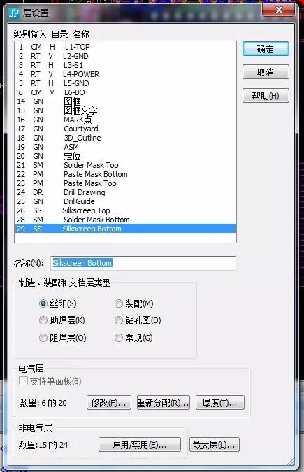
Then from this layer definition to see which layer of screen printing or solder resist is, for example:
The Silkscreen Top is the 26th floor; the Silkscreen Bottom is on the 29th floor, the Solder Mask Top is on the 21st floor, the Solder Mask Bottom is on the 28th floor, and then the correspondence is assigned to him in the corresponding object type.
For example, in the Pad Pad type, add the Solder Mask Top and the Solder MaskBottom to the two layers. Since the pad type is in principle no Silkscreen Top and Silkscreen Bottom, the pad is inside. You can not add silk screen layer correspondence. Then change to the following correspondence at 21 and 28 respectively.
21=PACKAGE GEOMETRY|SOLDERMASK_TOP
28=PACKAGE GEOMETRY|SOLDERMASK_BOTTOM
Pharmaceuticals,2-Methyl- Propanoic Acid Monohydrate Price,2-Methyl- Propanoic Acid Monohydrate Free Sample,Pure 2-Methyl- Propanoic Acid Monohydrate
Zhejiang Wild Wind Pharmaceutical Co., Ltd. , https://www.wild-windchem.com