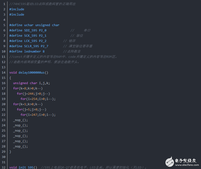
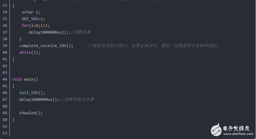
There is only one shift register, but there are 1+8, a total of 9 latches. Among them, the first latch can be understood as a transit pre-latch, it is not connected to Q0-Q7, and the next 8 latches are connected to Q0-Q7.
When the first time SCK and LCK, the shift register = the first data, and the pre-latch = the first data. But it did not enter the latches corresponding to Q0-Q7. Q0 to Q7=NON.
When SCK and LCK are used for the second time, the shift register = the second bit data, and the pre-latch = the second bit data. At the same time, the pre-latch updates the previous first bit data to the latch corresponding to Q0. At this time, Q0 = the first place. Q1 to Q7=NON.
When the third time SCK and LCK, the shift register = the 3rd bit data, and the pre-latch = the 3rd bit data. At the same time, the pre-latch updates the previous second bit of data to the latch corresponding to Q0, and Q0 gives the previous first bit of data to Q1, at this time Q0=the second bit. Q1=The first place. Q2 to Q7=NON.
After 8 cycles (after 8 SCK and 8 LCK are given), the shift register = the 8th bit data, and the pre-latch = the 8th bit data. But Q0-Q6 correspond to the 7th-1st data, the 8th data is not updated to Q0, and Q7=NON.
This is why the 8th digit data cannot always be displayed when the program is given 8 cycles.
Therefore, to display all 8 digits, SCK and LCK need to be given again.
So the problem is coming. Finally, SCK and LCK showed 8 digits. But: the 9th bit of useless data other than 8 bits is locked in the shift register and the pre-latch.
Then we can use SCLR (10 feet).
Just give SCLR a falling edge. This falling edge simultaneously clears the shift register and pre-latch. But it does not take effect immediately! It will take effect only when the next SCK is generated.
Therefore, in SCLR, the pre-latch and Q0-Q7 latches still lock the original data, and the output content will not be changed until the next SCK.
And when we send a new 8-bit data next time, at the first SCK, the new data will be received after the SCLR takes effect, because it will not affect the receiving of the new data.
I call this process "closing operation".
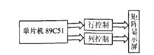
Each light is equivalent to a point in the coordinate map, with a unique and unique coordinate position, so that each light can be turned off and on through the signal of the pin.
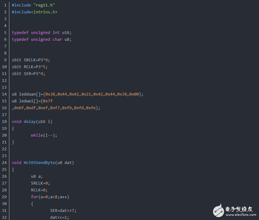
The col pin is connected to the eight pins of P0, and the row pin is connected to the eight-bit parallel output terminal of 595.
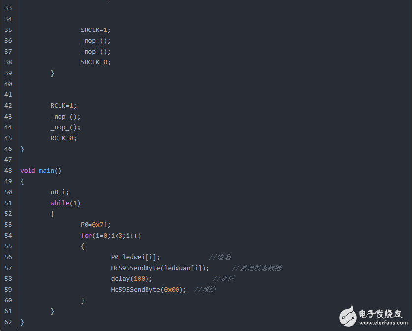
In the experiment, the display is column-by-column, eight columns are controlled by P0, and each column is displayed column-by-column through P0, during which the LED lights to be lit in each column are controlled by the 595 shift register.
74HC595 is a shift register with latch function in and out. In terms of image, pin 14 is a porter, pin 11 is a goalkeeper entering the factory, and 12 is a goalkeeper leaving the factory. When 11 has a rising edge, input one bit from pin 14 For data, when the rising edge of the 12-pin is repeated eight times, the previous eight-bit data is output from pins 1 to 7 to OE as the enable terminal, and the output is valid when it is low.
23.8 & 24 Inch Aio,Aio Pc,All In One Gaming Pc,Touch Screen Computer
Guangzhou Bolei Electronic Technology Co., Ltd. , https://www.nzpal.com