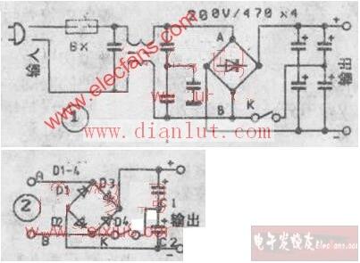
The following is a circuit diagram of the 220V to 110V circuit diagram
220v turn 110V circuit diagram
The filter capacitor of this circuit uses four 200V/470uF capacitor strings, which are connected in parallel to form a 100V/470uF capacitor, as shown in Figure 1. When K is closed, it is 110V voltage input. When K is off, it is 220V voltage input, and the output DC voltage is (220*2)V. The principle is shown in Figure 2. When K is disconnected, the circuit is a general full-wave rectifier circuit. When K is closed, set A+B one, then the current passes through A→D3→C1→B, so that c1 is charged with (110*2) V voltage; when A—B+, the current passes B→C2→D1→A C2 is charged with (110*2) V voltage. At this time, the output voltage is the sum of the voltages on C1 and C2 (220*2) V. In fact, this circuit is a voltage doubler rectifier circuit. Replace K with a two-way thyristor, plus a 110V/220V detection circuit to trigger the thyristor to turn on at 110V input, and turn off at 220V input, which can easily realize automatic conversion of 110V and 220V. .

- The Description of TV Antenna
-
In the Cable TV system, the task of the antenna is to receive the open channel TV signal or satellite TV signal in the air, and send it to the system for processing, transmission and distribution. Among them, the antennas receiving VHF and UHF open-circuit TV signals are called TV receiving antennas.
- TV receiving antenna is an important part of wireless TV signal receiving, and it is the gate for radio waves to enter the CATV system. There are two kinds of antenna: passive antenna and active antenna. The active antenna can make the antenna system realize high gain and high signal-to-noise ratio receiving.
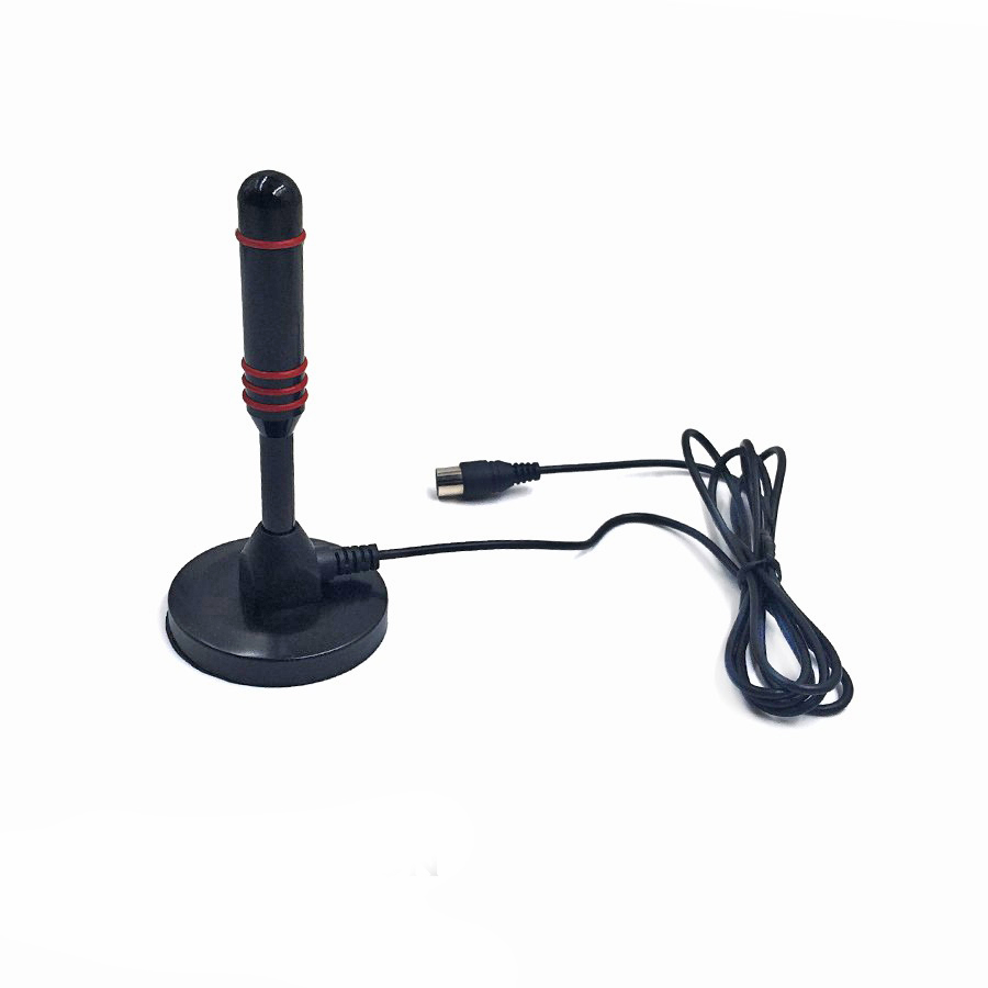
The Picture of TV Antenna


TV Antenna outdoor,TV Antenna Indoor,TV Antenna at best buy,TV Antenna Booster,TV Antenna Amazon
Yetnorson Antenna Co., Ltd. , https://www.xhlantenna.com